Pressurization System Presentation
The pressurization system, on the A320, normally operates automatically to adjust the cabin altitude and its rate of change, to ensure maximum passenger comfort and safety.
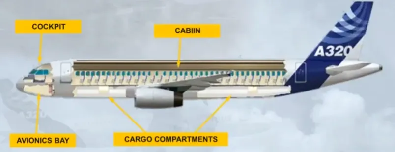
The pressurized areas are:
- The cockpit
- The avionics bay
- The cabin
- The cargo compartments.
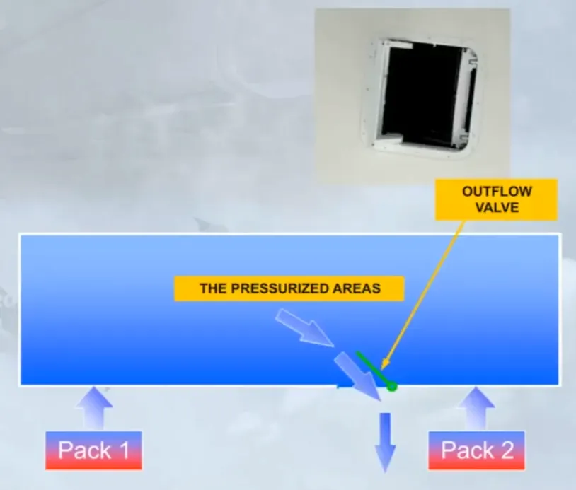
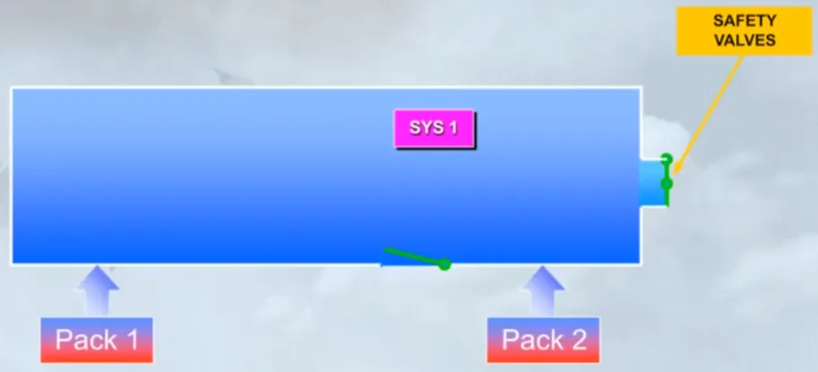
The concept of the system is simple. Air is supplied from the air conditioning packs to the pressurized areas.

An outflow valve is used to regulate the amount of air allowed to escape from the pressurized areas.
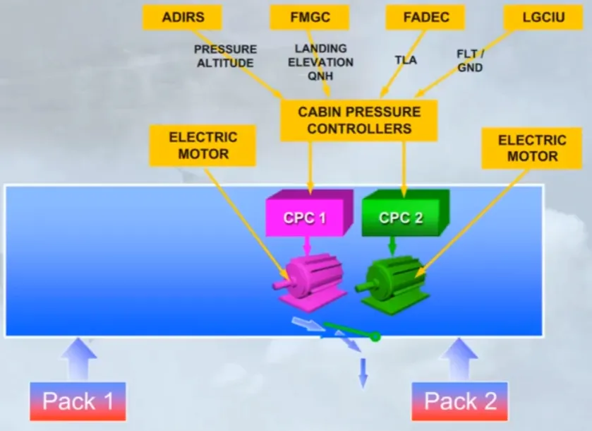
Automatic control of the outfow valve is provided by two Cabin Pressure Controllers (CPC). Each controller has an electric motor to move the outflow valve.
Note: the CPC receives data from the Air Data Inertial and Reference System (ADIRS). the Flght Management and Guidance Computer (FMGC), the Full Authority Digital Engine Control (FADEC) and the Landing Gear Control and Interface Unit (LGCIU) in order to elaborate the different pressurization control laws.
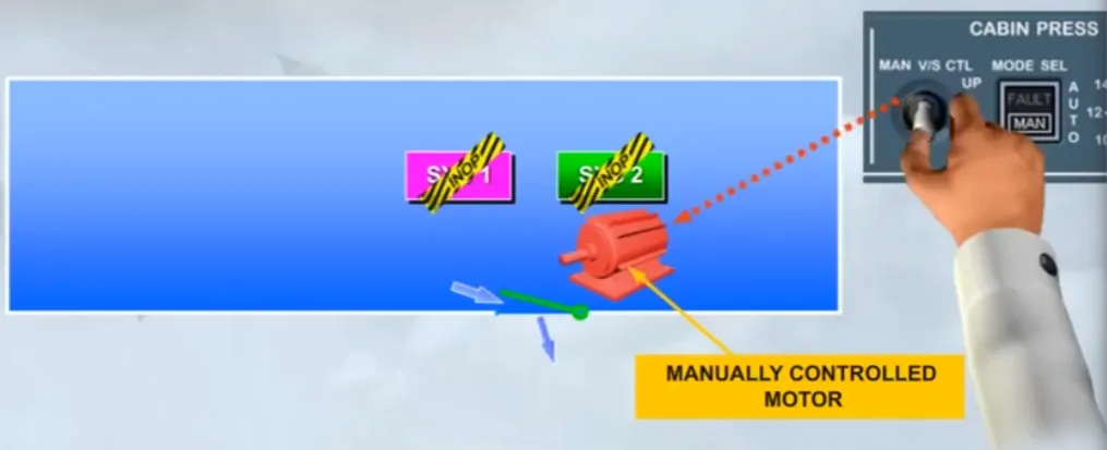
A controller/ motor combination is known as a system. Only one system will operate at any one time with the other system acting as backup.

A third motor is installed for use in the event of both automatic systems failing and requires a manual input to open or close the outflow valve.
Two independent pneumatic safety valves are installed at the rear pressure bulkhead, above the flotation line, and they operate to avoid a cabin differential pressure from going too high or too low.
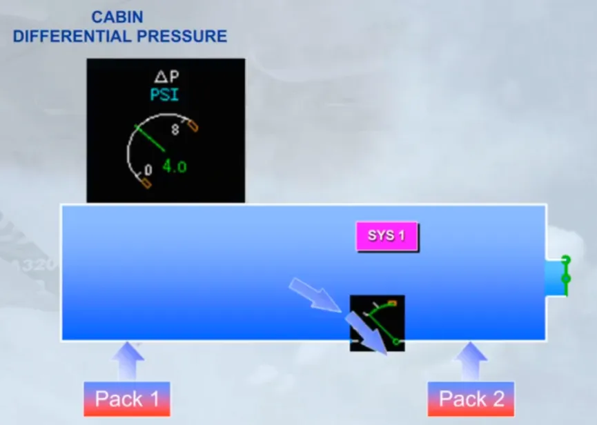
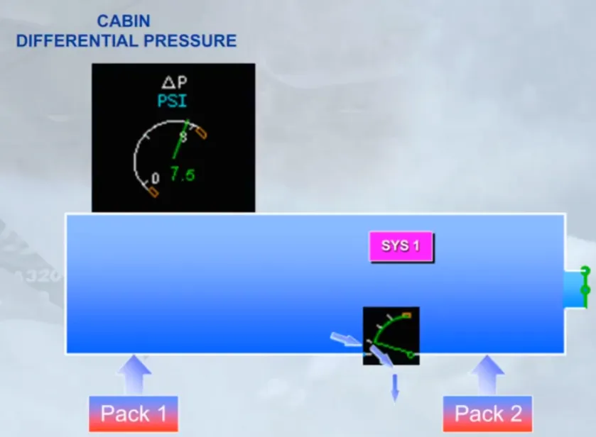
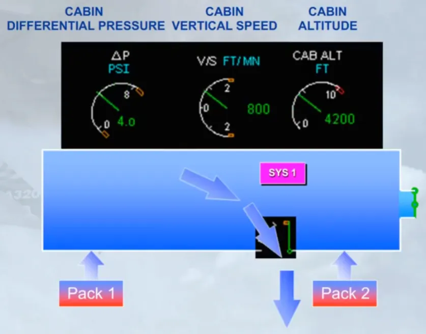
Let us look at the operation of the outflow valve for an aircraft in cruise and what happens to cabin Differential Pressure, cabin altitude, and cabin Vertical Speed. We will start with cabin Differential Pressure. If the outflow valve is closed, or only allowing a small amount of air to escape, then the cabin Differential Pressure will increase.
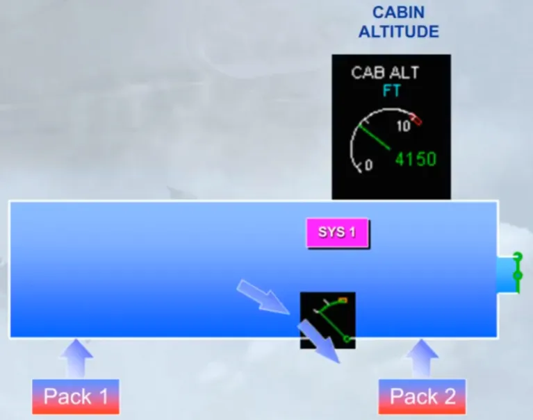
Now let’s look at what happens to cabin altitude.
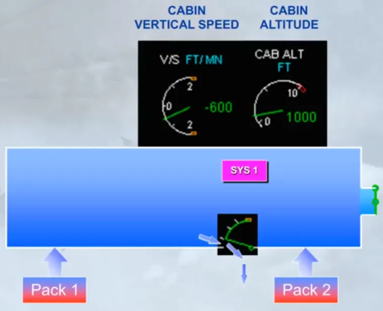
If the outflow valve is closed, or only allowing a small amount of air to escape, then the cabin altitude will descend.
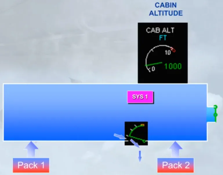
We can also see what the cabin is doing by reference to Vertical Speed. When the outflow valve closes the cabin altitude will decrease (negative Vertical Speed).
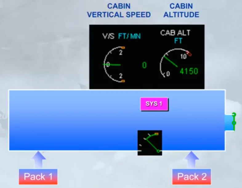
If the outflow valve is fully open, a lot of air is allowed to escape, the cabin pressure will decrease, the cabin altitude will climb (positive Vertical Speed).
The crew can monitor all cabin pressure functions on the ECAM CAB PRESS page.
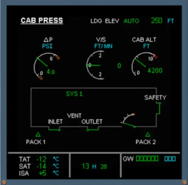
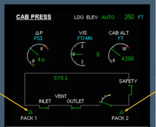
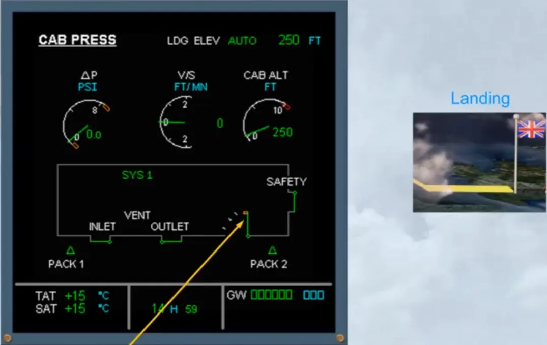
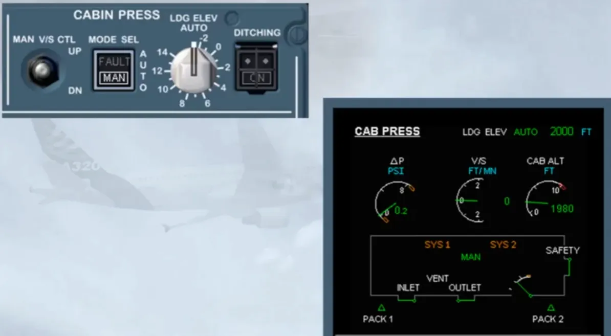
Let’s look at the information, related to the pressurization system, that is presented on the CAB PRESS page. The pack indication is displayed green when the related pack is on.
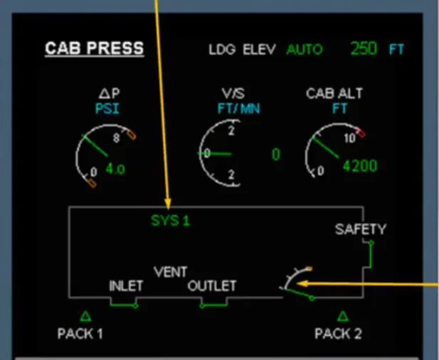
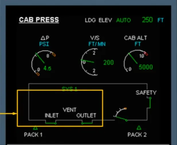
The outflow valve position can be monitored, and the system controller in use is shown.
There is a single indication for the safety valves. We will look at how this indication changes later in the module.
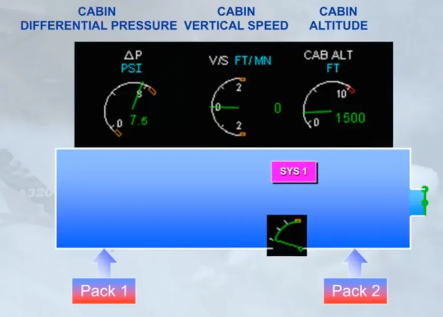
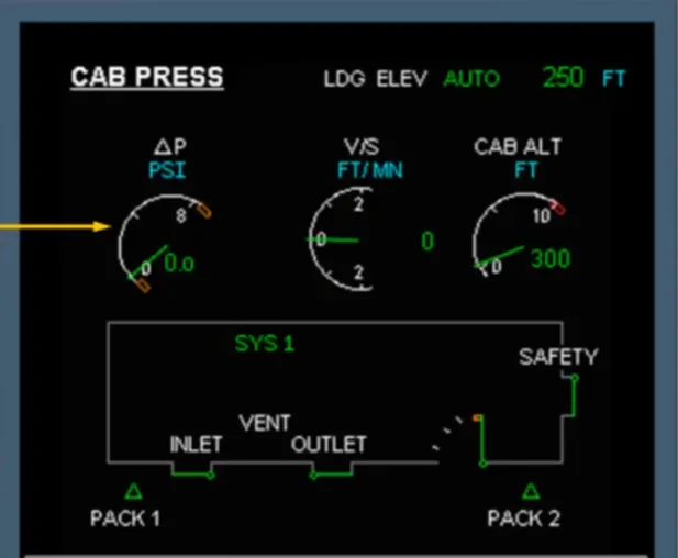
The cabin Differential Pressure, or ΔP, shows the difference, in psi, between the cabin pressure and external pressure. This differential pressure will be at zero on the ground and increase as the aircraft climbs.
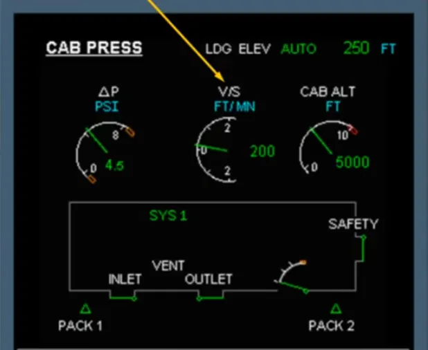
The cabin Vertical Speed shows the rate of change, in Feet per minute, of cabin altitude. For passenger comfort the pressurization system will aim to keep this rate of change as small as possible.
The cabin altitude is also shown.
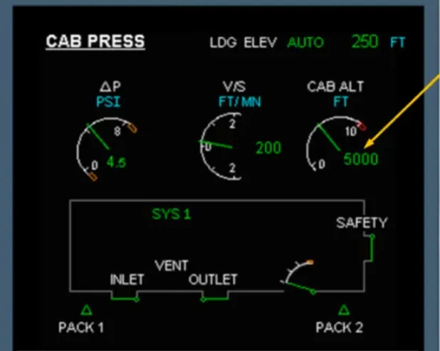
The VENT, the INLET and the OUTLET indications are related to the avionics ventilation system and will be discussed later.
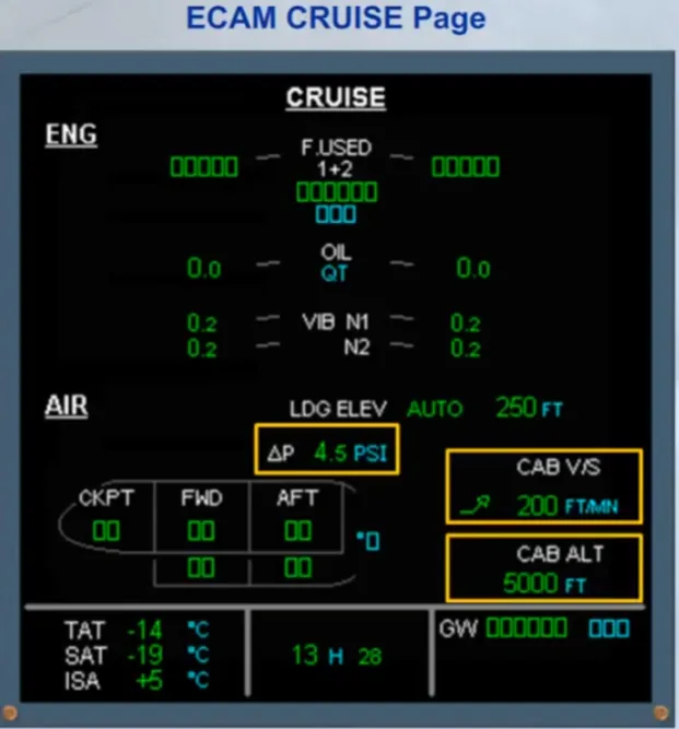
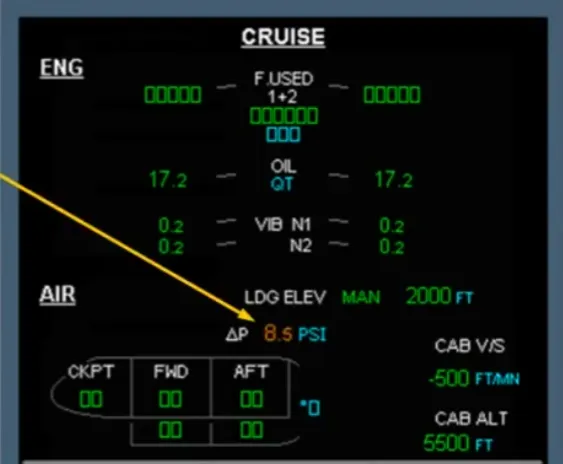
On the ECAM cruise page there are indications of:
- Cabin differential pressure
- Cabin vertical speed
- Cabin altitude.
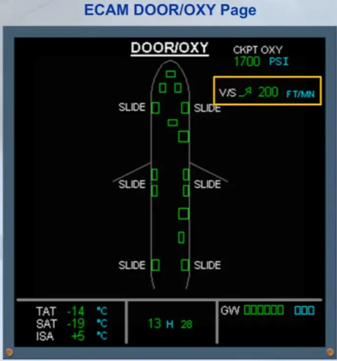
There is also an indication of cabin Vertical Speed on the ECAM door page. Note that this indication is only displayed when the aircraft is airborne.
On the overhead panel there is a CABIN PRESS panel containing controls to operate the pressurization system. Under normal conditions no pilot action is required on this panel during flight.
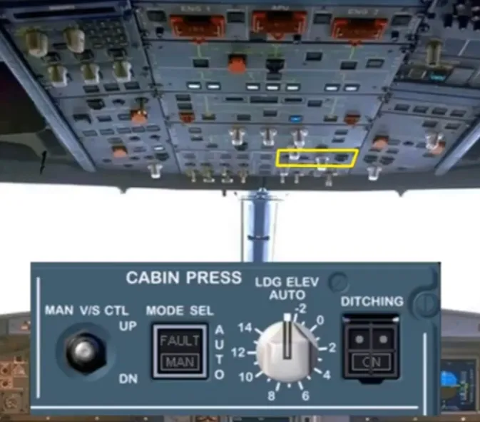
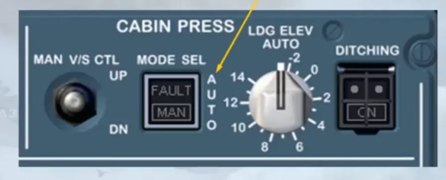
The pressurization MODE SEL pb-sw has two settings:
- Automatic
- Manual.
The normal position for this pb-sw is “lights out”. In this position the pressurization system is in AUTO mode.
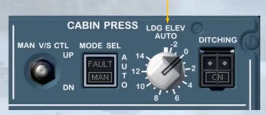
The LDG ELEV selector normally remains in the AUTO position. Landing elevation, which is required by the pressurization system, is then provided by the FMGS based upon elevation of the destination airport. If the landing elevation is not available from the FMGS, then it can be set manually using this selector.
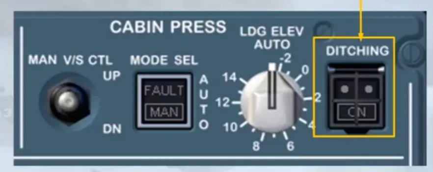
The guarded DITCHING pb-sw is provided to close all valves below the waterline so that the aircraft can be sealed in the unlikely event of a ditching.
For a better understanding of how the pressurization system works, we will go through a normal fight profile, paying particular attention to the ECAM indications.
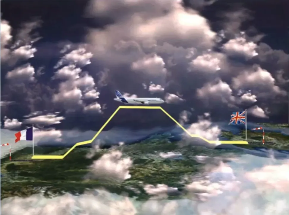
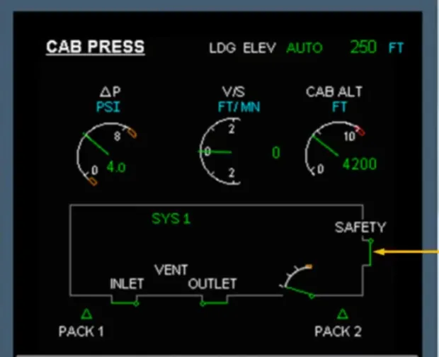
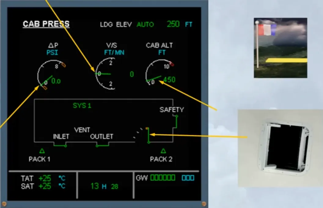
When the aircraft is on the ground before the flight, the outflow valve is fully open, there is no differential pressure and there is no vertical speed.
We can also notice that the cabin altitude is indicating the field elevation of the departure airfield.
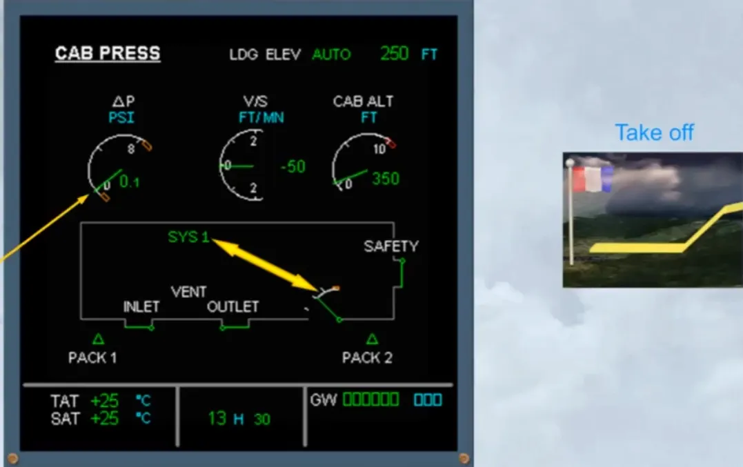
During the Take off roll, the system controller signals the outflow valve to close slightly in order to pre-pressurize the aircraft.
This is to avoid a pressure surge at rotation.
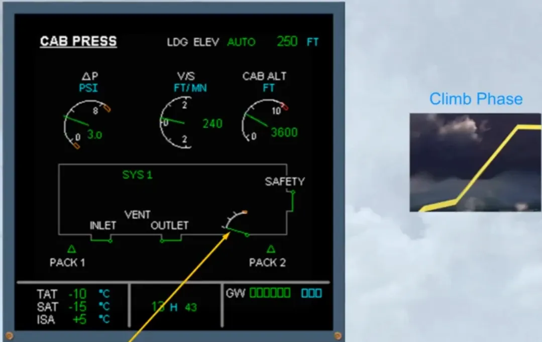
At lift-off the controller initiates the climb phase and cabin altitude varies according to a fixed law taking into account the actual rate of climb of the aircraft. The outflow valve will move as required to achieve this.
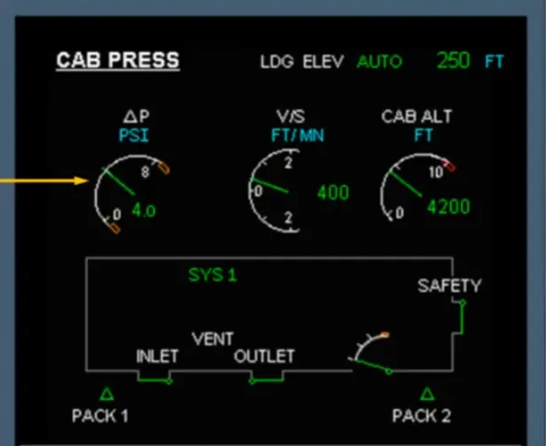
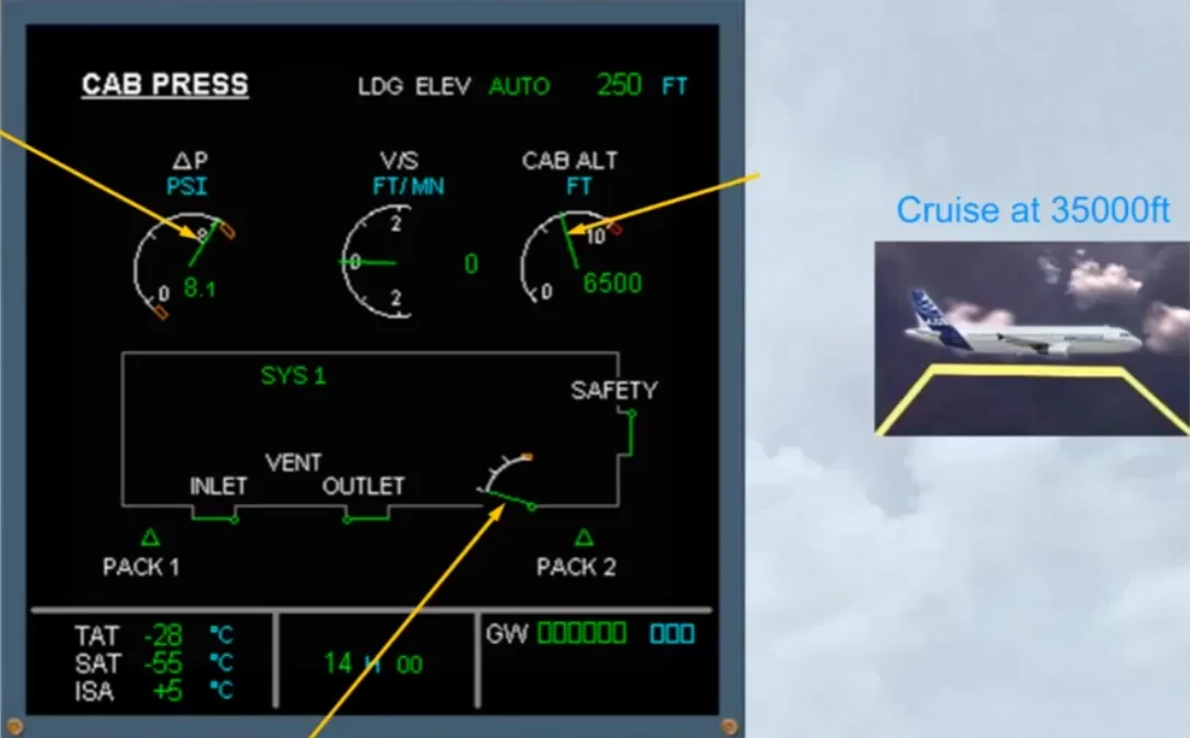
Once established in cruise, the cabin altitude and differential pressure will remain steady. The outfliow valve will move as required to maintain the cabin altitude. In the example shown the aircraft is in cruise at 35 000 feet. Notice the values of differential pressure and cabin altitude.
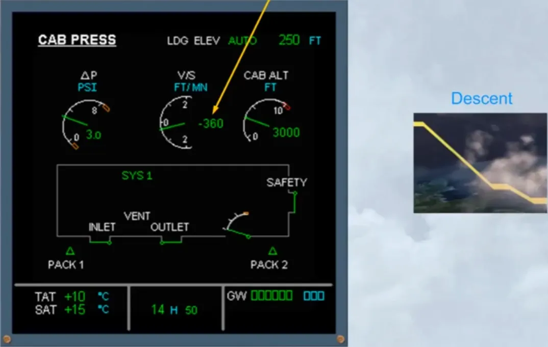
During the descent phase the pressure rate is optimized so that the cabin reaches landing field pressure just prior to landing.
Note: for passenger comfort the automatic function will limit the rate of cabin descent to a maximum of approximately 750 feet per minute.
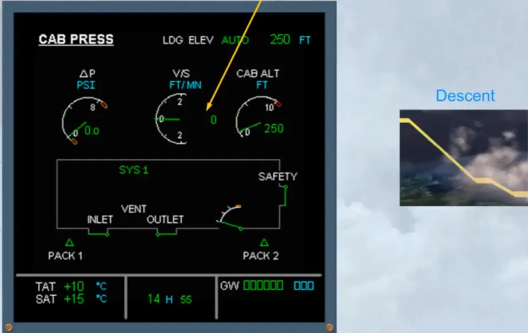
At touchdown the cabin altitude should be at the airfield elevation, and there should be no residual pressure.
To ensure this, few seconds after touchdown, the outflow valve fully opens by the active controller.
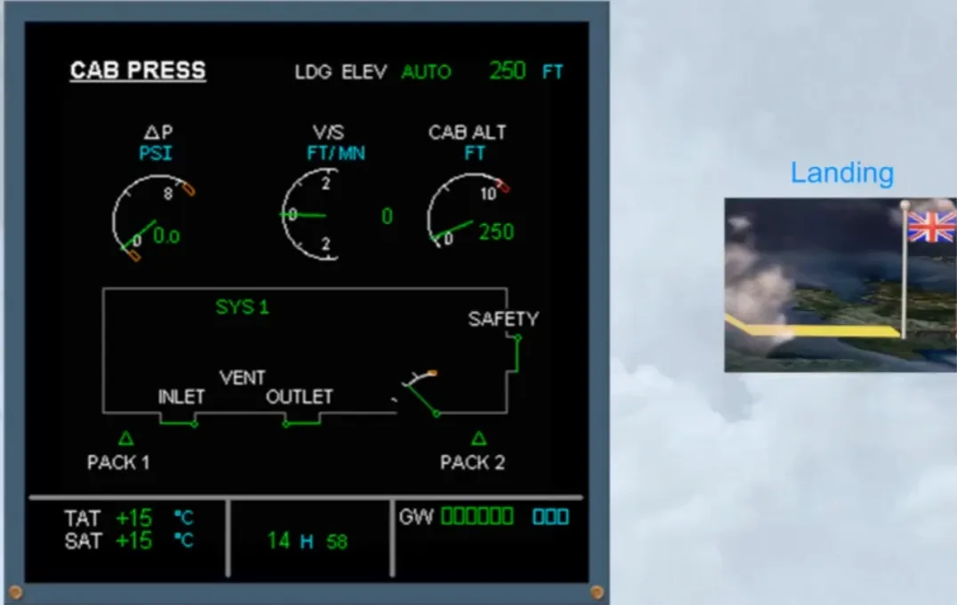
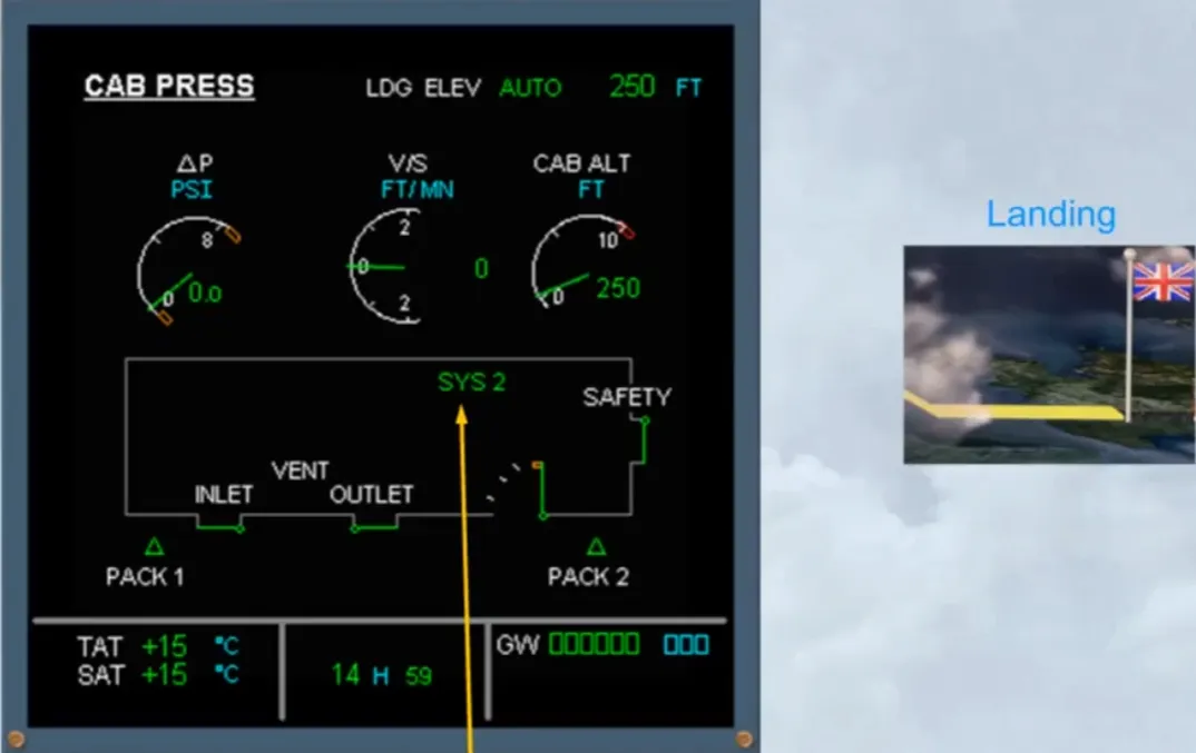
Few seconds after the outflow valve is fully open, an automatic change over of the system controllers occurs in preparation for the next flight. This happens so that both systems are used equally.
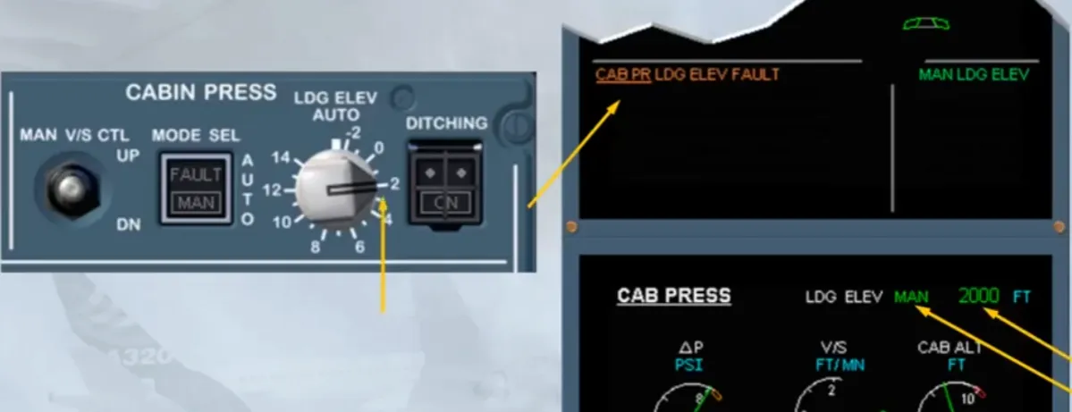
Let’s now review some failure cases. The caution CAB PR LDG ELEV FAULT is telling you that the pressurization system has, for some reasons, lost the landing elevation data normally supplied by the FMGS.
Notice that depending on the version, the landing elevation details on the system page are blanked, or are replaced by amber XX or by zero.
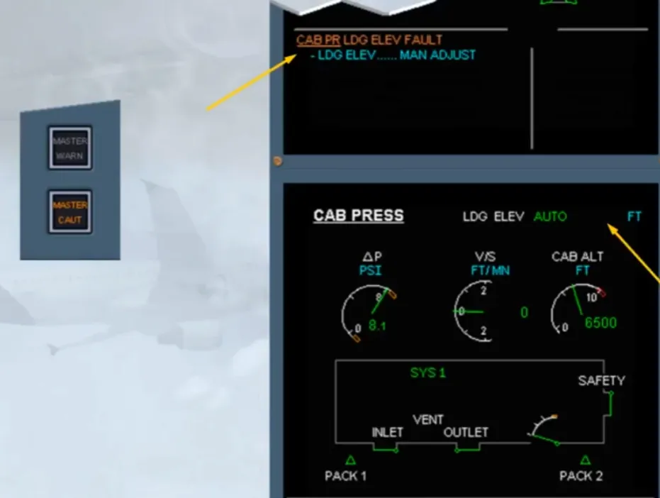


Read the actions on the EWD.
In this case, the procedure asks to set the landing field elevation manually with the LDG ELEV selector.
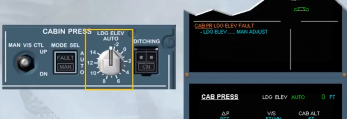
As the soon as the selector is moved from the AUTO position, the action line on EWD clears and a MAN message appears on the CAB PRESS page. The LanDinG ELEVation value will also indicate the selected value.
To complete this module let’s look at some other abnormal indications.
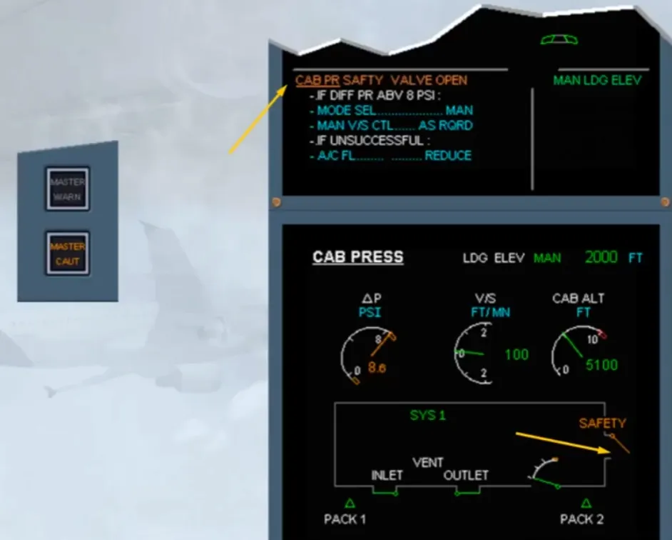
The safety valves, prevent the cabin pressure from going too high, or too low.
An ECAM caution CAB PR SAFETY VALVE OPEN is generated, if one of the safety valves has been detected open for more than 1 minute.
Notice that the safety valve indication on the CAB PRESS page changes to amber.
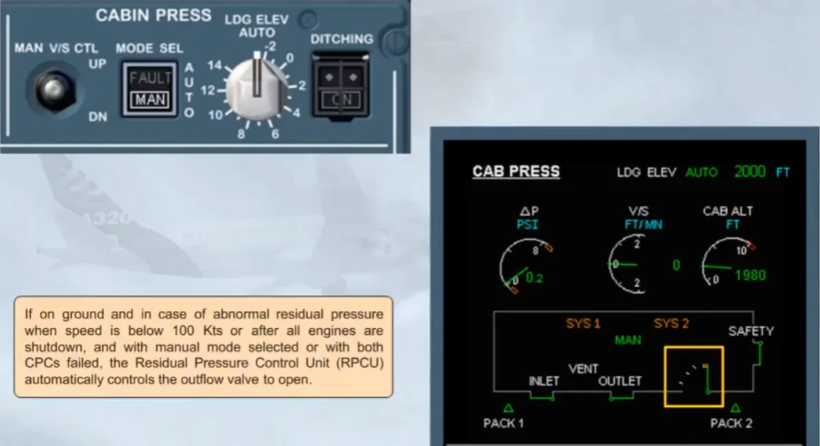
If on ground and in case of abnormal residual pressure when speed is below 100 Kts or after all engines are shutdown, and with manual mode selected or with both CPCs failed, the Residual Pressure Control Unit (RPCU) automatically controls the outflow valve to open.
Module completed
Video study
Section titled “Video study”- Watch the video available on YouTube