EFIS ND Presentation
The Navigation Display (ND), can present the pilots with a lot of useful data to assist in the safe operation of the aircraft.
Because the ND gives the pilots a visual presentation of where the aircraft is in relation to airfields, navaids, etc, the operation of the aircraftis also made easier.
In this module we will use the Captain’s ND.
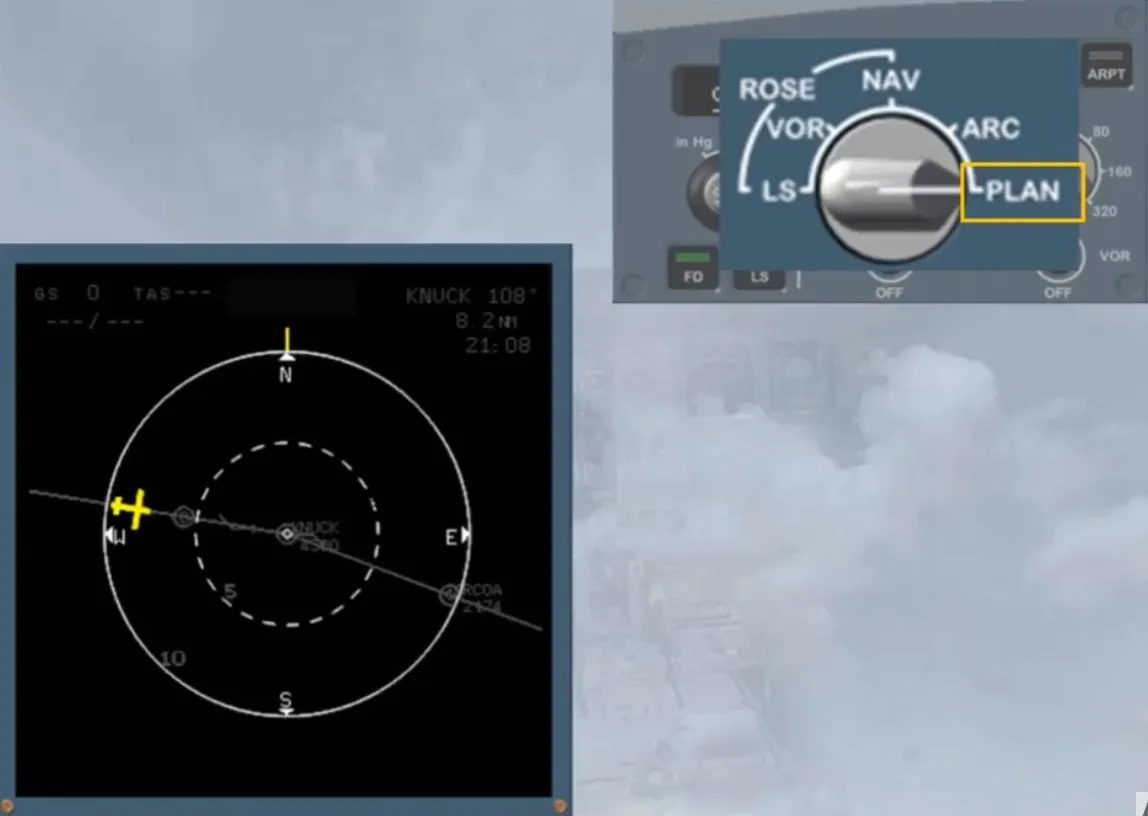
There are 5 display modes available on the ND. They are selected by the mode selector on the EFIS control panel.
Note: For training purposes, the other information has been dimmed.
There are 3 basic navigation display modes, which display in the background:
- A 360 degree compass ROSE
- A 90 degree segment ARC
- A map PLAN with the north at the top.
Before moving on to look at the individual modes, let’s quickly look at some common information.
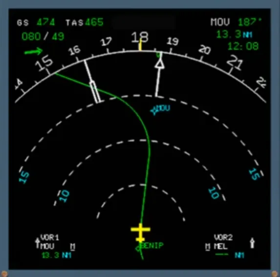
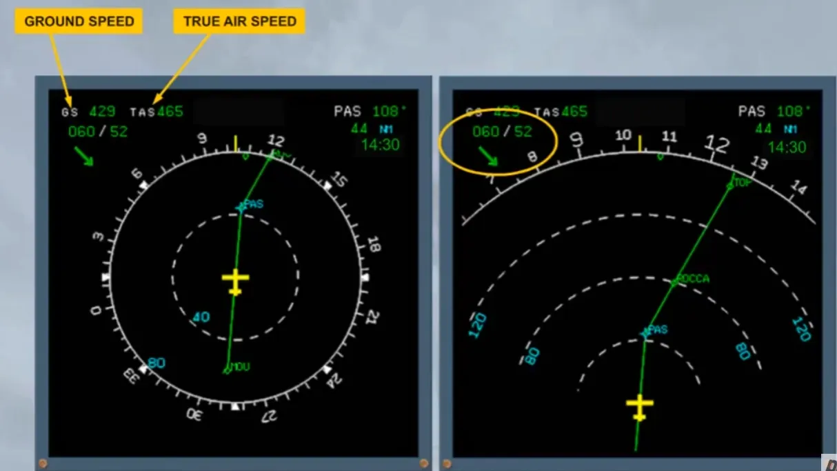
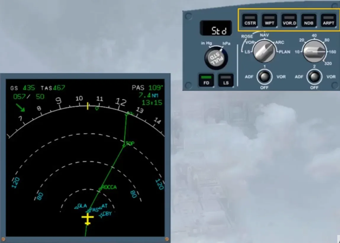
The Ground Speed (GS) and the True Air Speed (TAS) are permanently displayed on the top left corner.
Below the speed indications, is the wind data: wind direction (true north), wind speed and an arrow to indicate the wind direction with respect to magnetic north. Here, wind from 60 degrees at 52 kt.
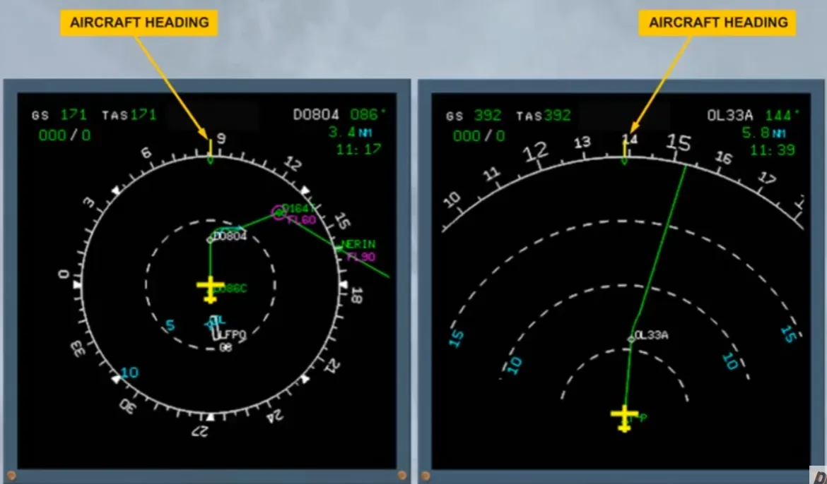
The aircraft magnetic heading is given by a fixed yellow lubber line against the moving compass rose.
The selected heading or track (if BIRD is selected ON) is shown by a blue triangle or blue numbers if out of display range. This is similar to the PFD.
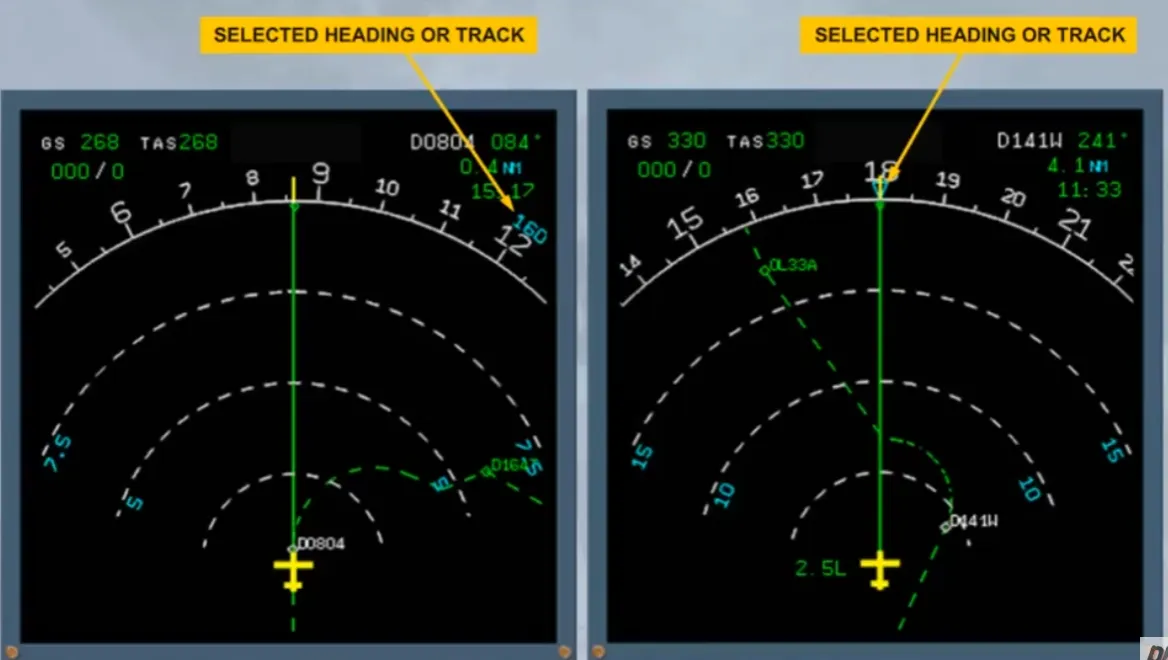
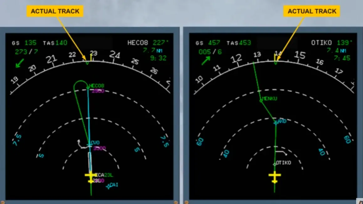
Actual track is depicted by a green track diamond.
Range marks are displayed by white dotted lines while range values are depicted in blue.
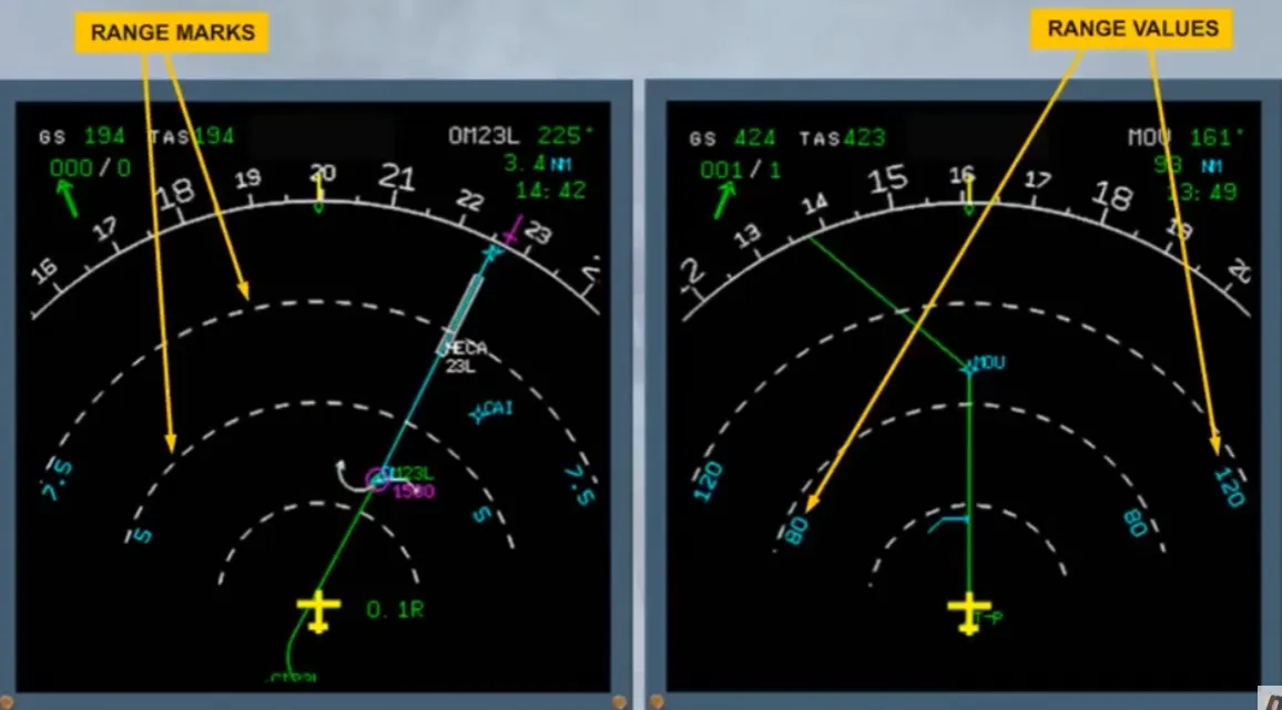
The display range can be adjusted using the range selector.
Select 320 mile range.
You can now see more of your flight plan and that the range values have changed accordingly.
Let’s study the ND individual modes.
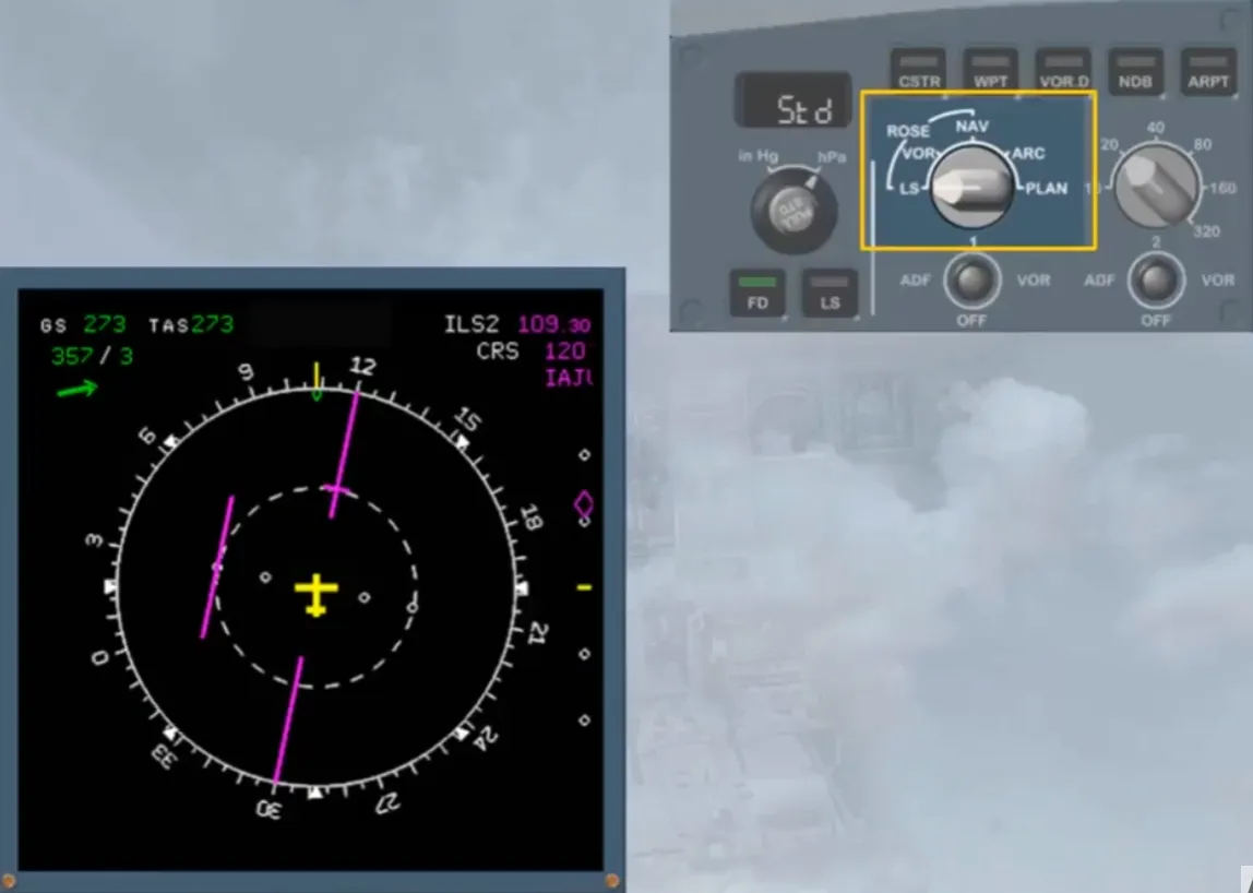
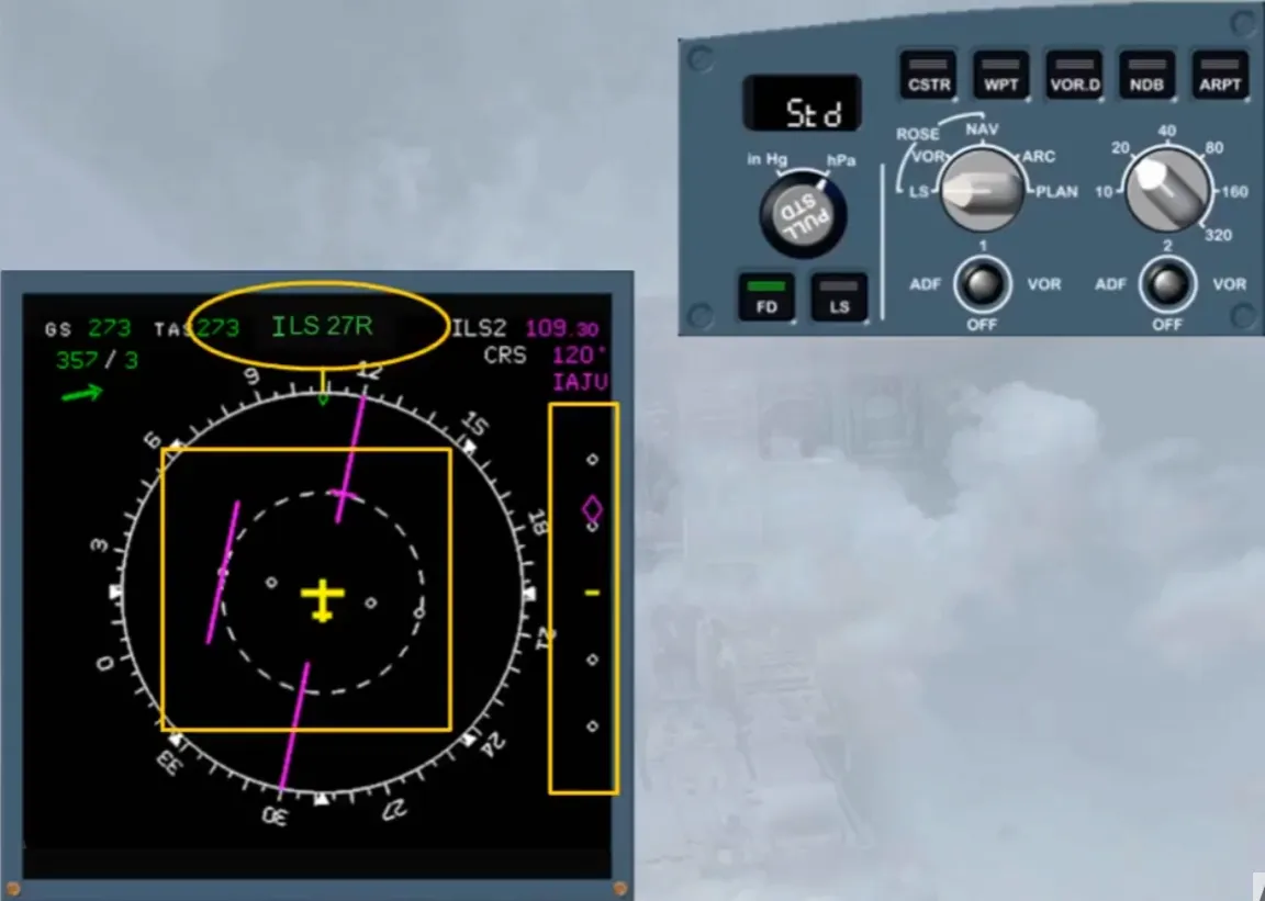
The ROSE ILS mode is a raw data mode providing standard localizer and glide slope deviation bars.
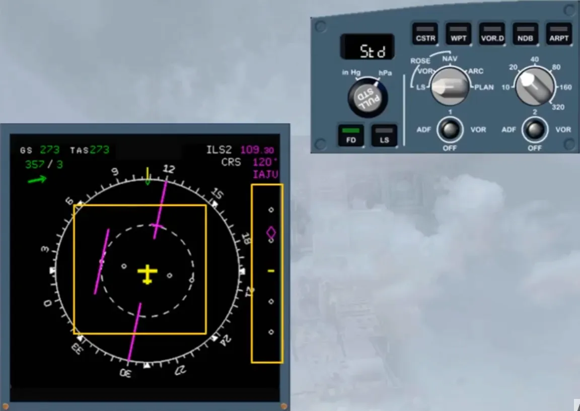
Note: The full runway name of the MCDU selected approach will be displayed if, in the related FMS phase, the along track distance to destination is less than 250 NM.
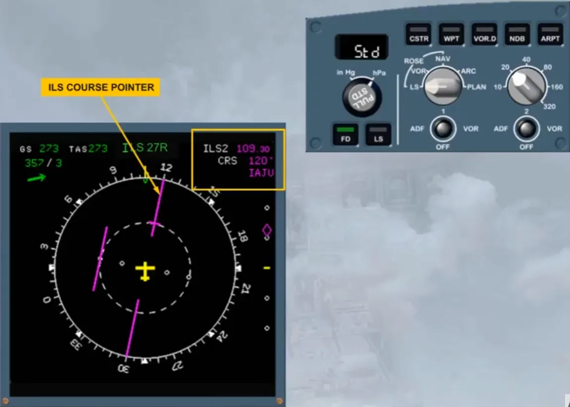
Other information is displayed to assist you:
- An ILS course pointer
- ILS information.
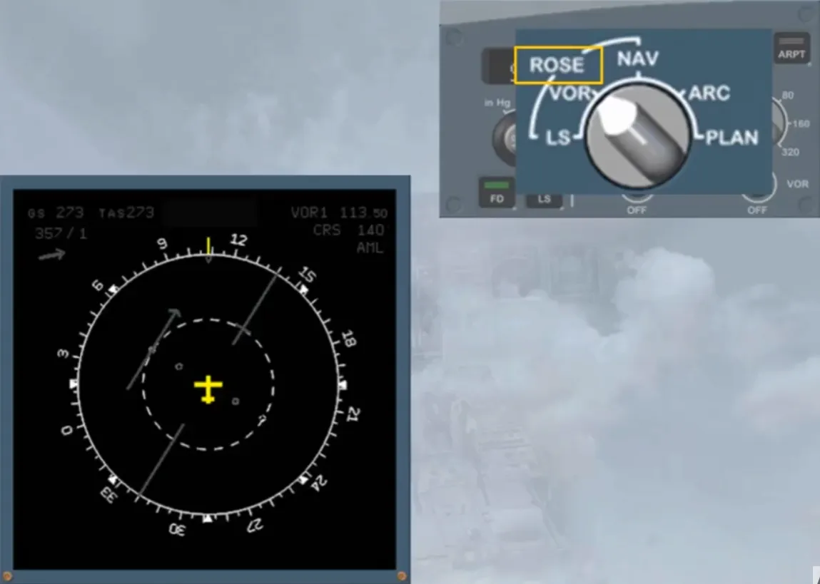
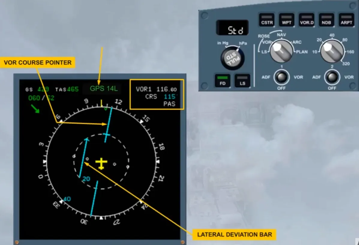
Select ROSE VOR mode.
The ROSE VOR mode is another raw data display.
On the display, there is now a course pointer and a lateral deviation bar for the VOR. In this case, VOR 1. To have this display, a course must have been selected on the MCDU RAD NAV page.
Like ROSE ILS, the information about the tuned frequency, the selected course and which navaid, (here”PAS”) is displayed in the top right hand corner. Also the MCDU selected approach type (VOR or GPS) is displayed as shown.
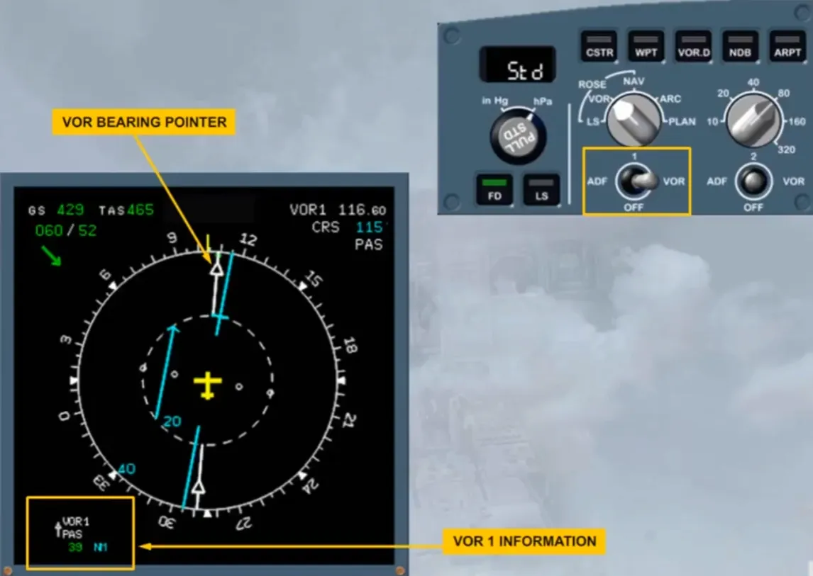
Let’s now display the VOR bearing pointer.
Select VOR 1.
Notice that there is a white VOR bearing pointer and VOR information associated with the pointer. This information is available even if a course hasn’t been selected on the MCDU RAD NAV page.
The number one pointer is represented by a single line.
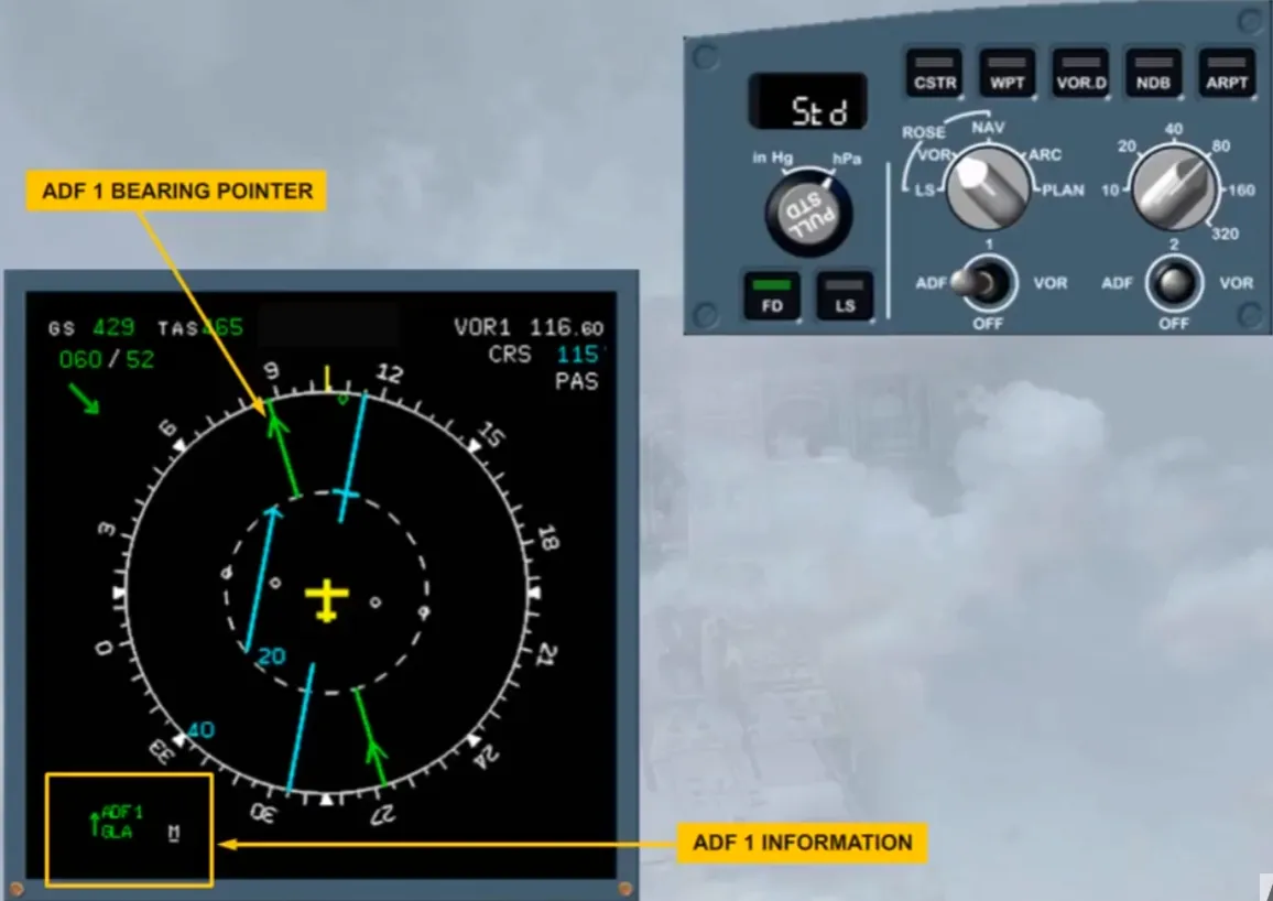
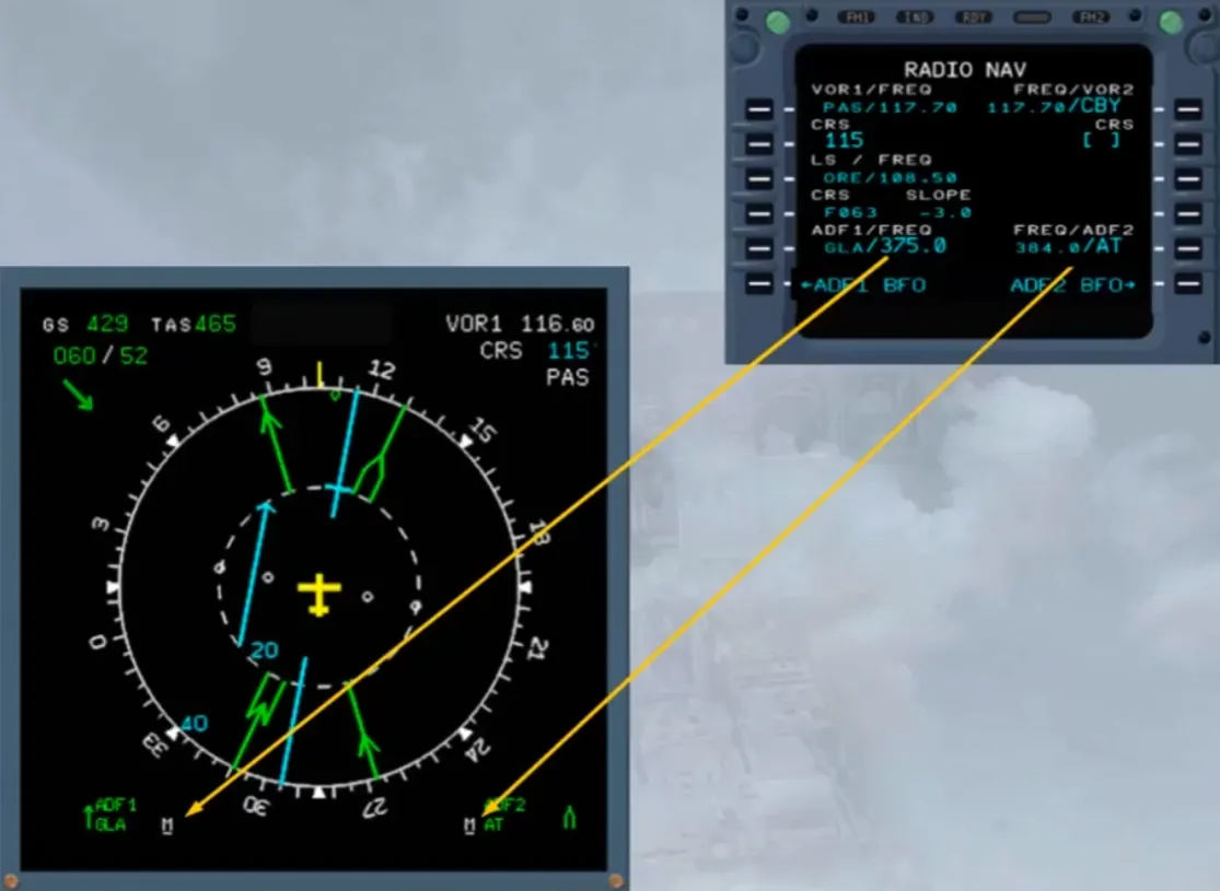
Let’s change the selection on the EFIS control panel to display ADF 1 instead of VOR 1. This is achieved by moving the number one ADF VOR selector to ADF. We will do it for you.
The white VOR bearing pointer has been replaced by a green ADF bearing pointer. The VOR information on the bottom left of the display has been replaced by ADF 1 information.
Notice that the selection of the pointer has not removed the deviation information for VOR 1.
We will now display the ADF 2 bearing pointer, by selecting ADF/VOR selector 2 to ADF.
The ADF 2 bearing pointer is now displayed represented by a double lined arrow.
At the bottom of the display there is information on the selected nav aids.
Notice that, in common with most things on the aircraft, it is number 1 on the left and number 2 on the right.
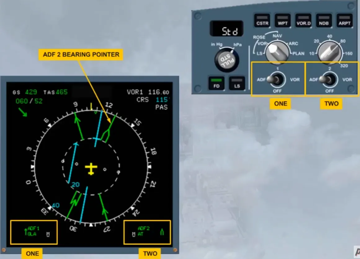
Notice the tiny underlined “M” beside the NAVAID information which indicates that each ADF has been manually tuned by the pilots on the MCDU RAD NAV page.
You will learn more about the NAVAID tuning in the ATA 34 Navigation chapter.
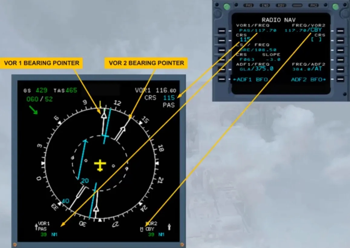
To see the effect of the ADF-VOR selectors, select both VOR bearing pointers on.
The two white VOR bearing pointers are now visible. As you can see on the RAD NAV page, the VOR 1 is auto tuned with its course manually entered and the VOR 2 is manually tuned.
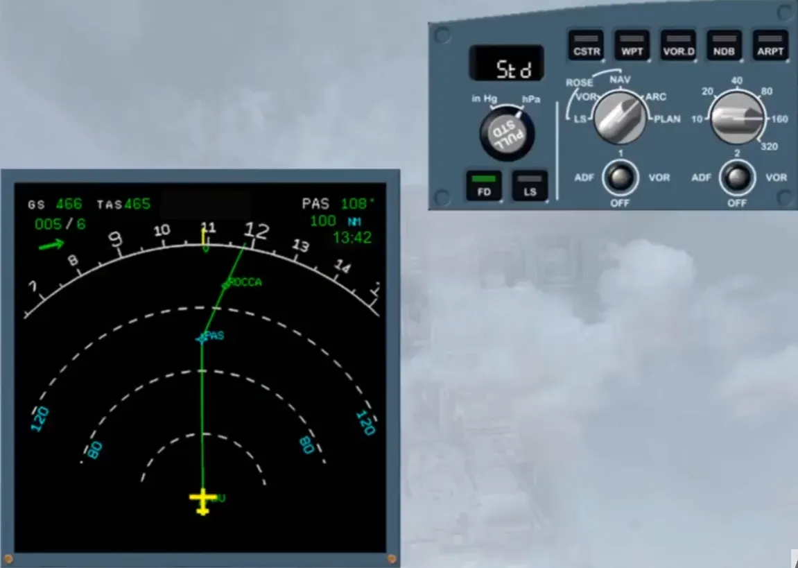
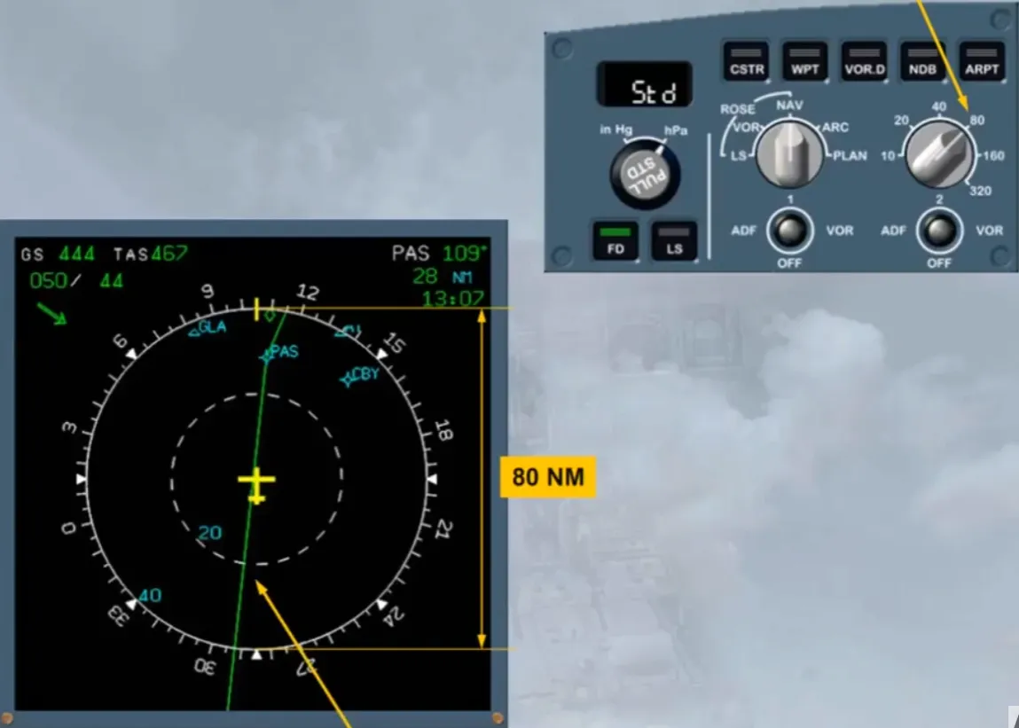
You have seen the two raw data displays. Now let’s look at the ROSE NAV display.
A map view of the area surrounding the aircraft, is now displayed.
On the EFIS control panel, the range selector is set at 80 nm. It is the distance from the bottom to the top of the compass rose.
The green line represents the flight plan. It will be studied in the ATA 22 -Auto flight chapter.
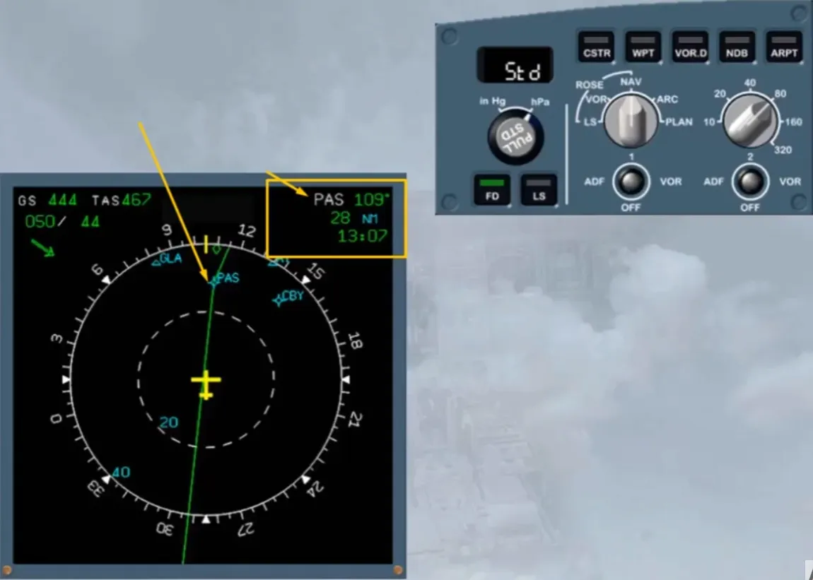
The information contained in the top right hand corner of the display relates to the TO waypoint.
The information is:
- Track to waypoint
- Distance to go
- ETA (Estimated Time of Arrival) at waypoint.
In this example, the TO waypoint is PAS and is also displayed on the map view.
Note: As the TO waypoint is a tuned navaid it is in blue instead of in white.
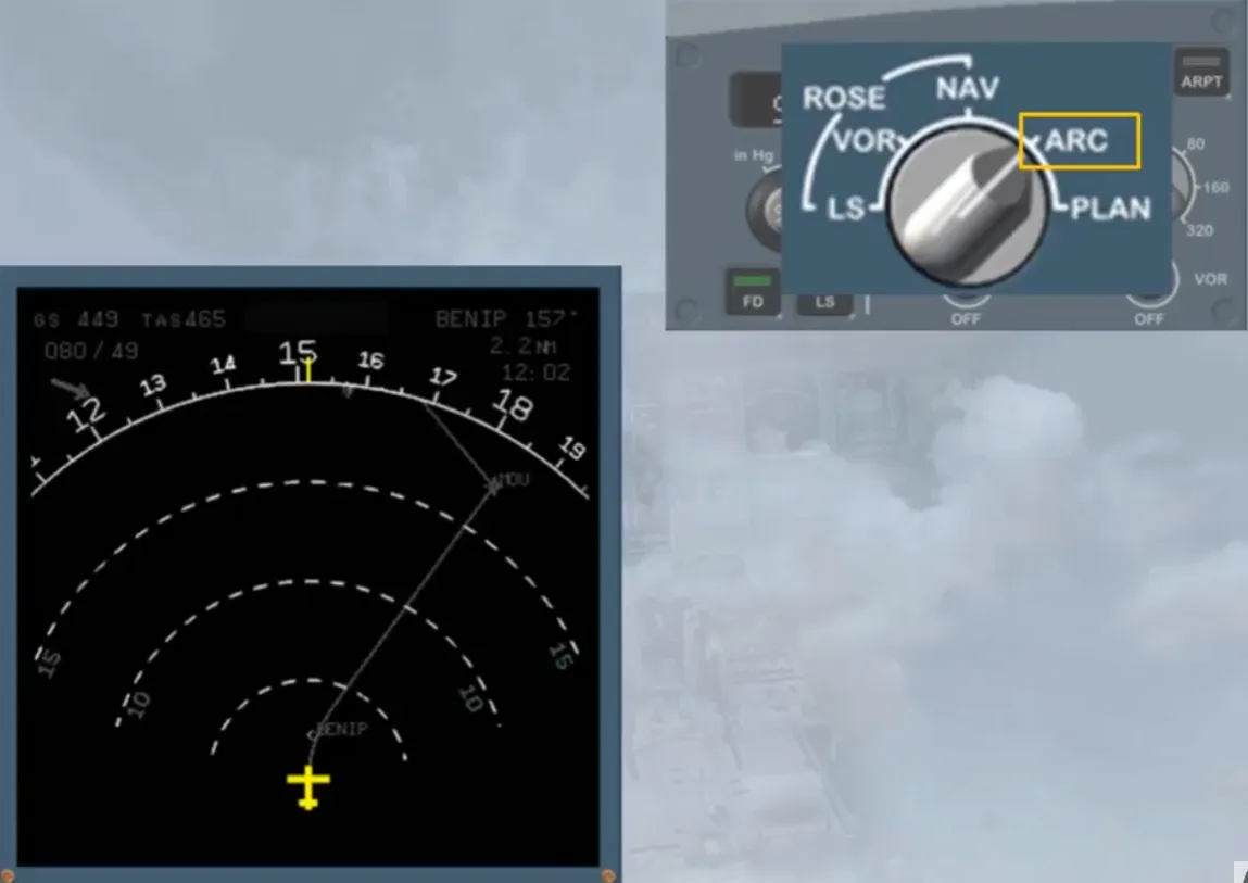
The normal mode for the cruise phase is the ARC mode. Select the ARC mode with a range of 160 nm.
Using the pushbuttons at the top of the EFIS control panel, additional information can be displayed, for example airports that are in the displayed range.
Select airport. Agreen light illuminates in the pb.
On the display, the airports contained in the aircraft’s database, and within the area, are shown.
This is a useful feature when considering diversions.

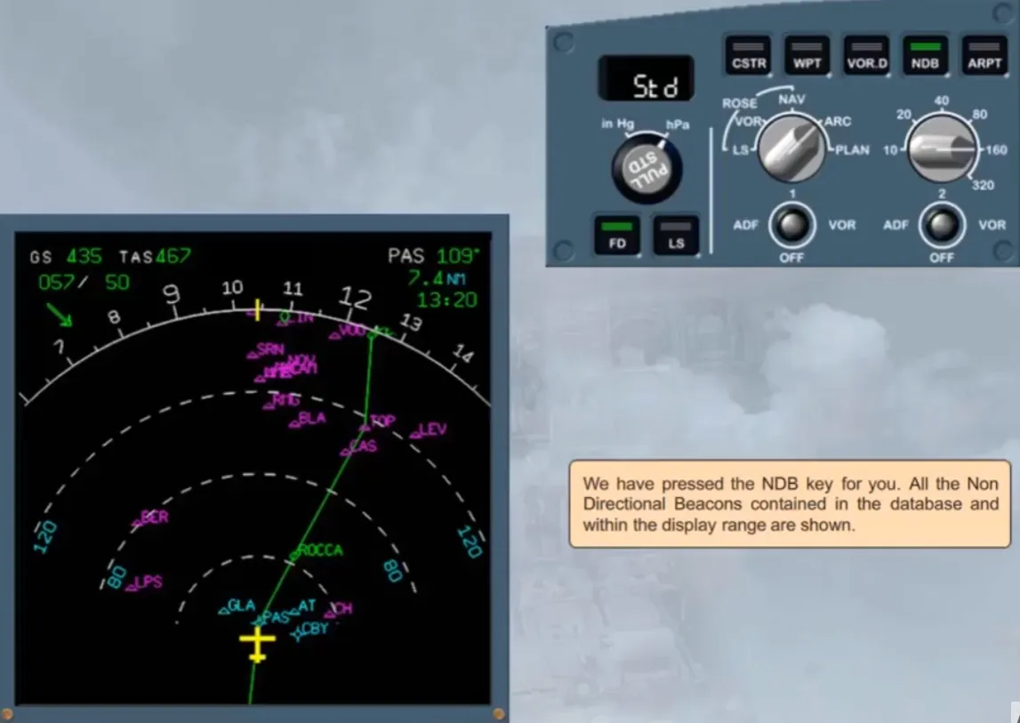
We have pressed the NDB key for you. All the Non Directional Beacons contained in the database and within the display range are shown.
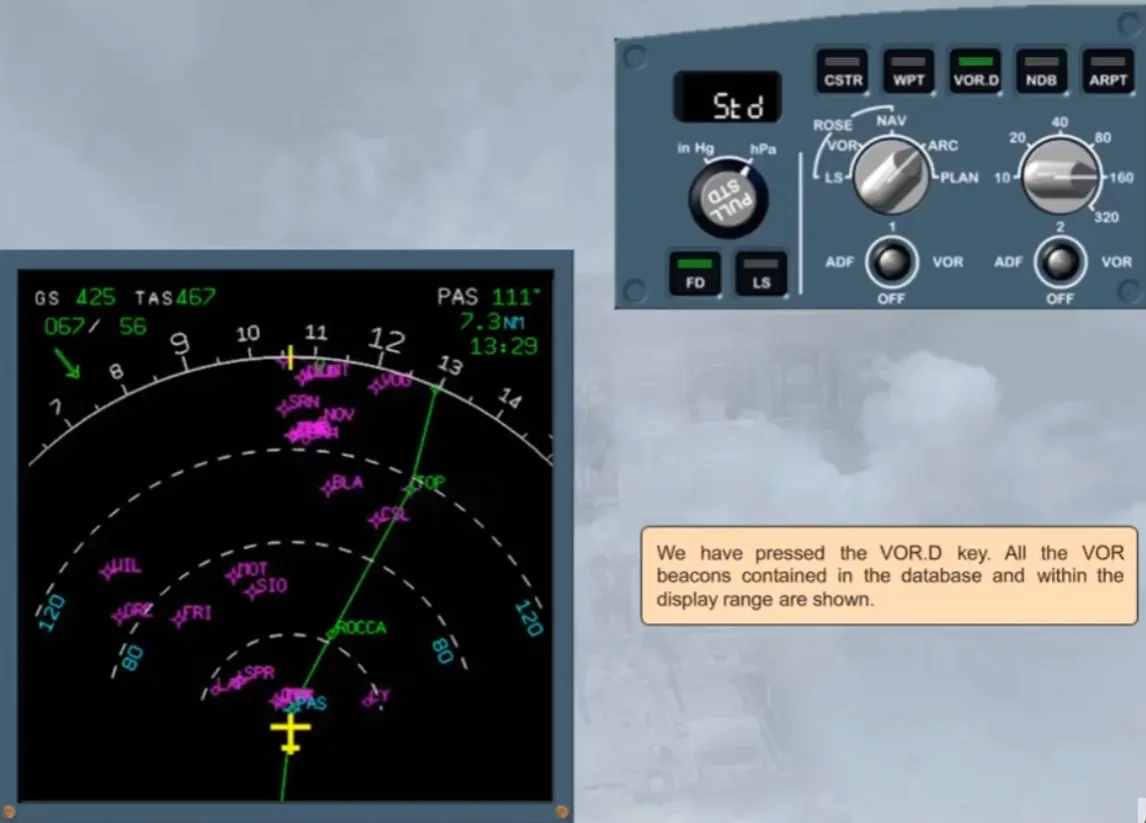
We have pressed the VOR.D key. All the VOR beacons contained in the database and within the display range are shown.
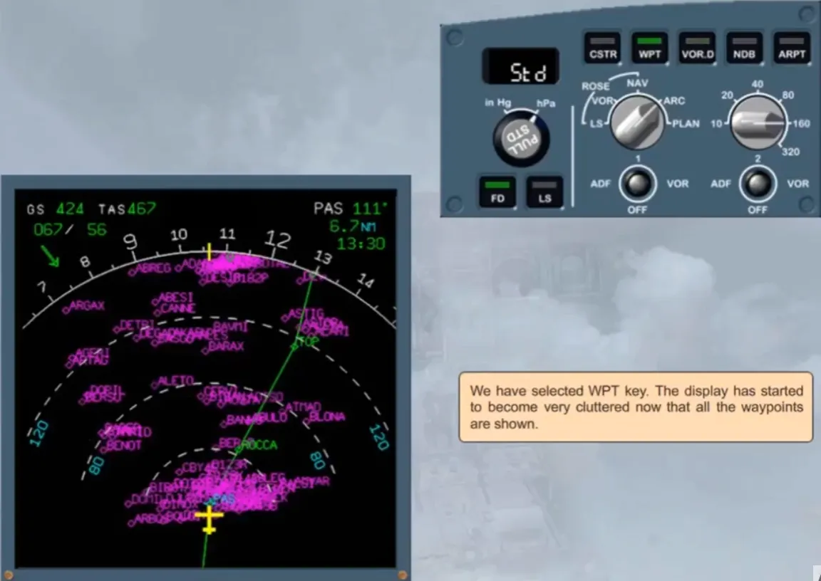
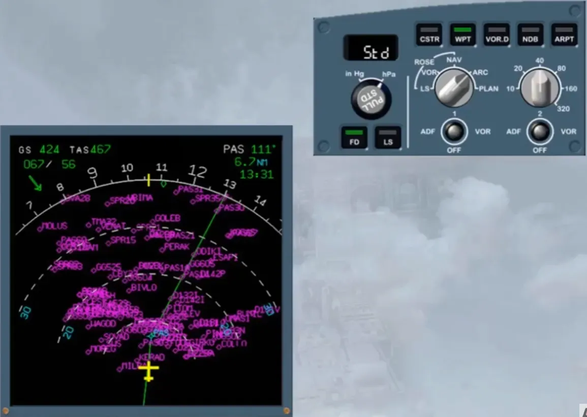
We have selected WPT key. The display has started to become very cluttered now that all the waypoints are shown.
We have turned the range selector to 40 for you. As you can see the display is a little less cluttered. Now let’s look at the final display mode.
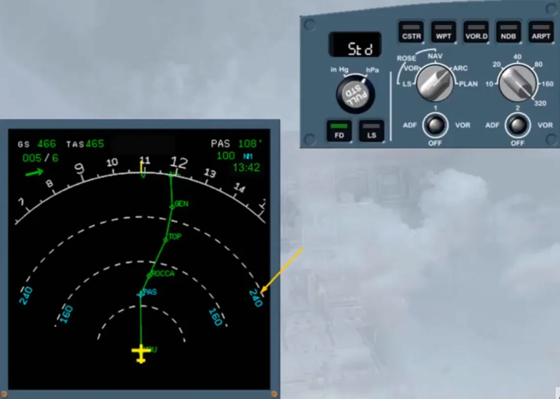
Select plan mode.
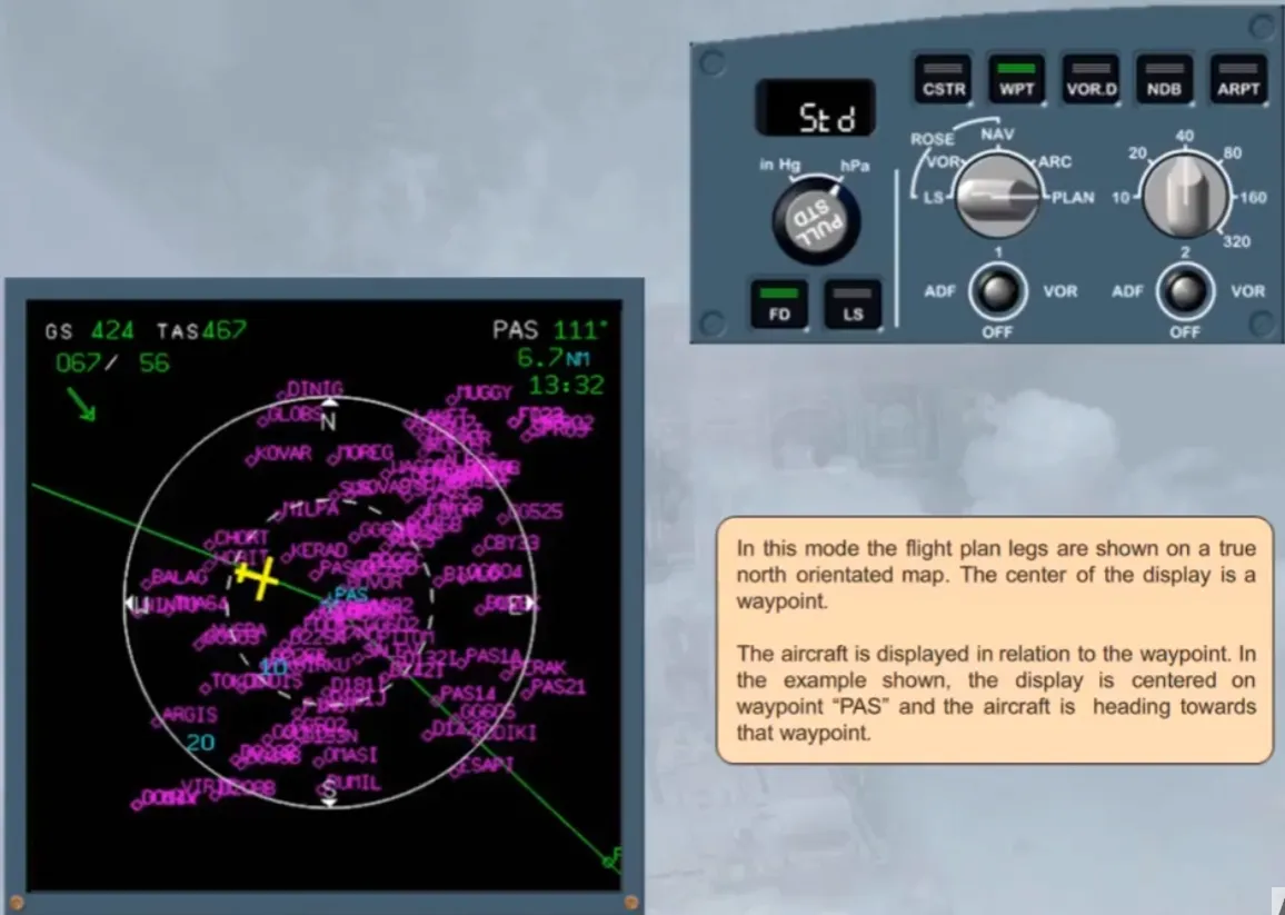
In this mode the flight plan legs are shown on a true north orientated map. The center of the display is a waypoint.
The aircraft is displayed in relation to the waypoint. In the example shown, the display is centered on waypoint “PAS” and the aircraft is heading towards that waypoint.
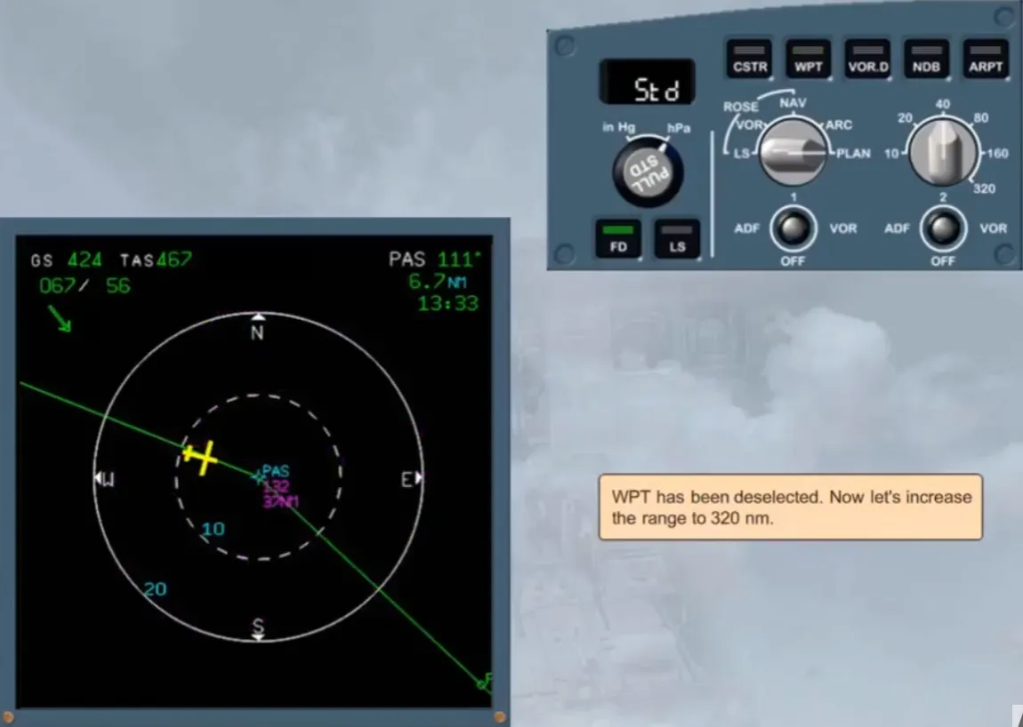
WPT has been deselected. Now let’s increase the range to 320 nm.
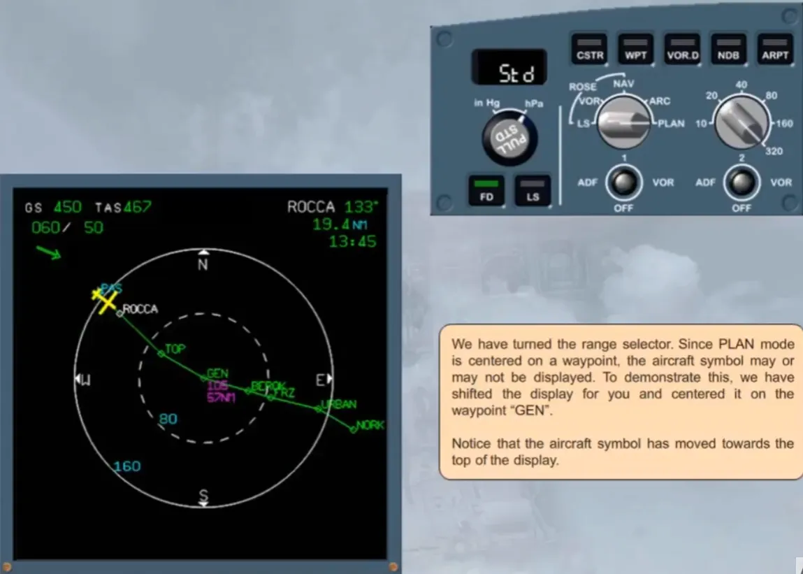
We have turned the range selector. Since PLAN mode is centered on a waypoint, the aircraft symbol may or may not be displayed. To demonstrate this, we have shifted the display for you and centered it on the waypoint “GEN”.
Notice that the aircraft symbol has moved towards the top of the display.
Module completed
Video study
Section titled “Video study”- Watch the video available on YouTube