Air Conditioning Operation
Let’s assume that you are about to start the flight.
The APU is running and you require Air Conditioning.

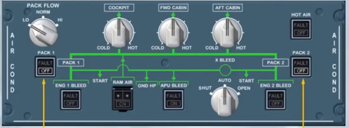
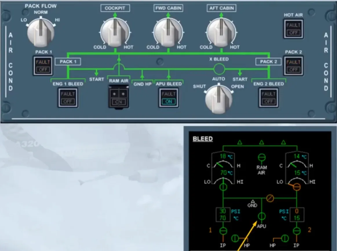
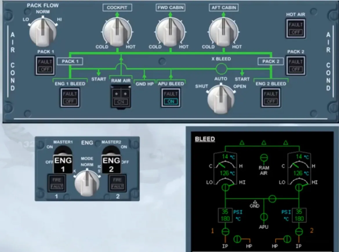
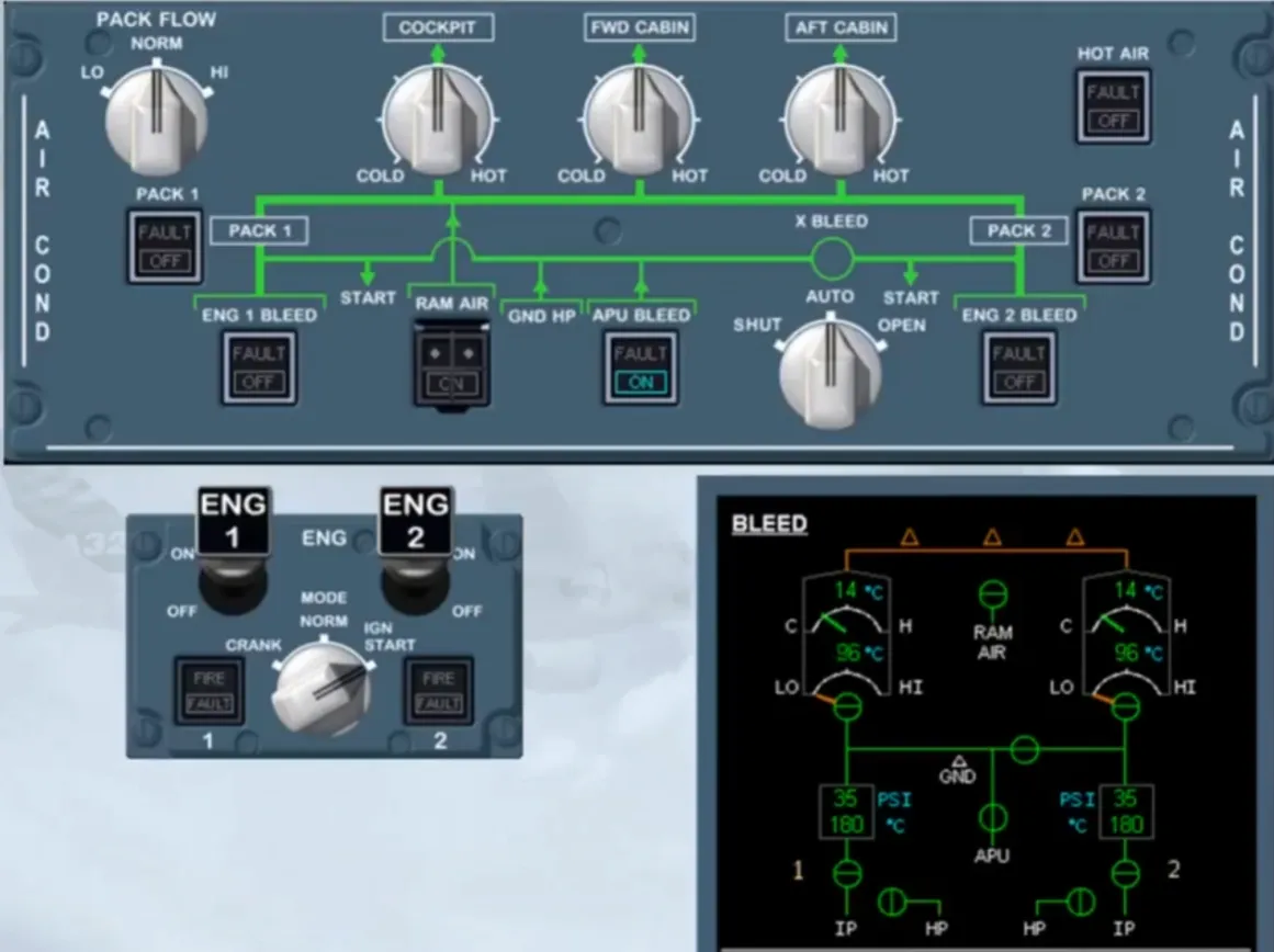
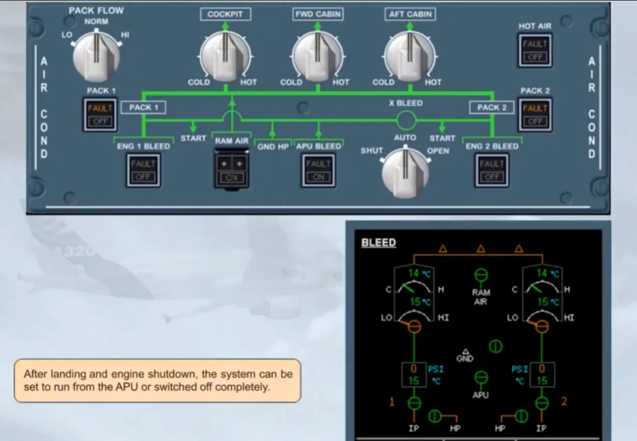
You are now in the cockpit, and this is how you find the AIR COND panel during your scanning sequence. Notice that, except for the OFF lights on the two PACK pushbutton switches, all other pushbuttons are in the normal lights out position.
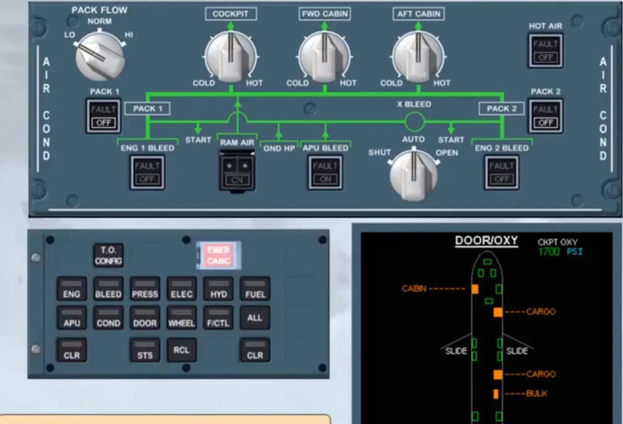
One step of the cockpit preflight check is to extinguish all white lights on the overhead panel. So that you can watch what is happening, let’s have a look at the ECAM BLEED page.
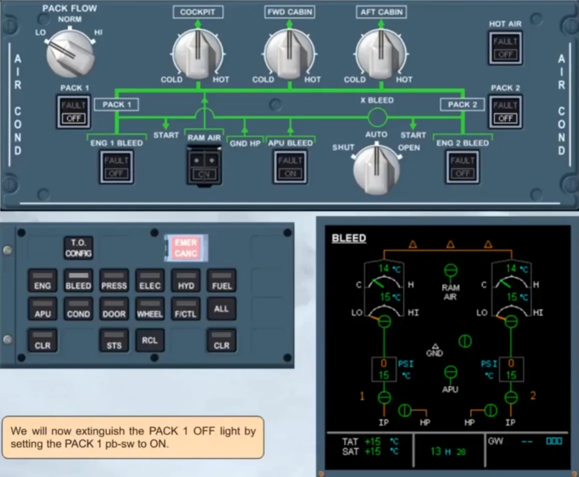
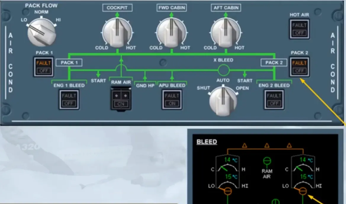
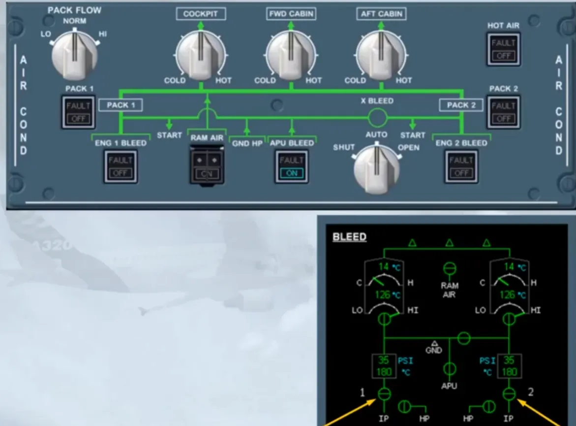
We will now extinguish the PACK 1 OFF light by setting the PACK 1 pb-sw to ON.
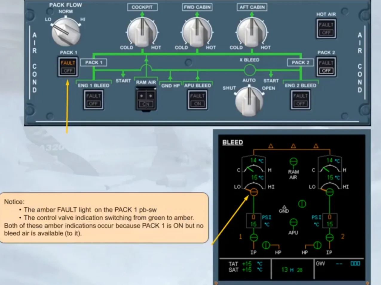
Notice:
- The amber FAULT light on the PACK 1 pb-sw
- The control valve indication switching from green to amber.
Both of these amber indications occur because PACK 1 is ON but no bleed air is available (to it).
We have set the PACK 2 pb-sw to on for you. As for PACK 1, there is no available bleed air to PACK 2.
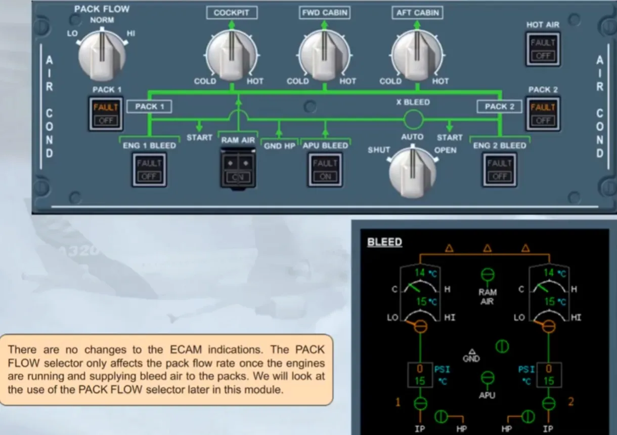
Since you are expecting a standard passenger load, the PACK FLOW selector can be set to NORM.
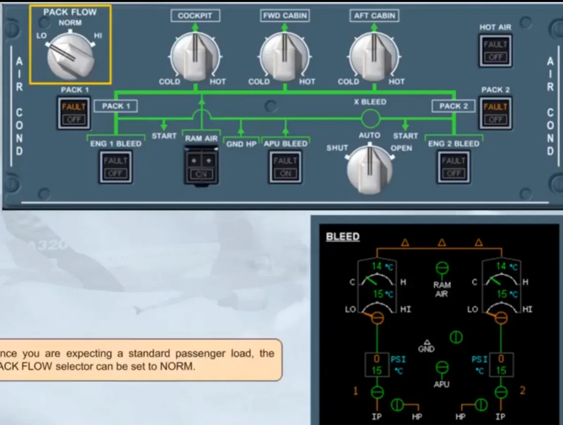
There are no changes to the ECAM indications. The PACKFLOW selector only affects the pack flow rate once the engines are running and supplying bleed air to the packs. We will look at the use of the PACK FLOW selector later in this module.
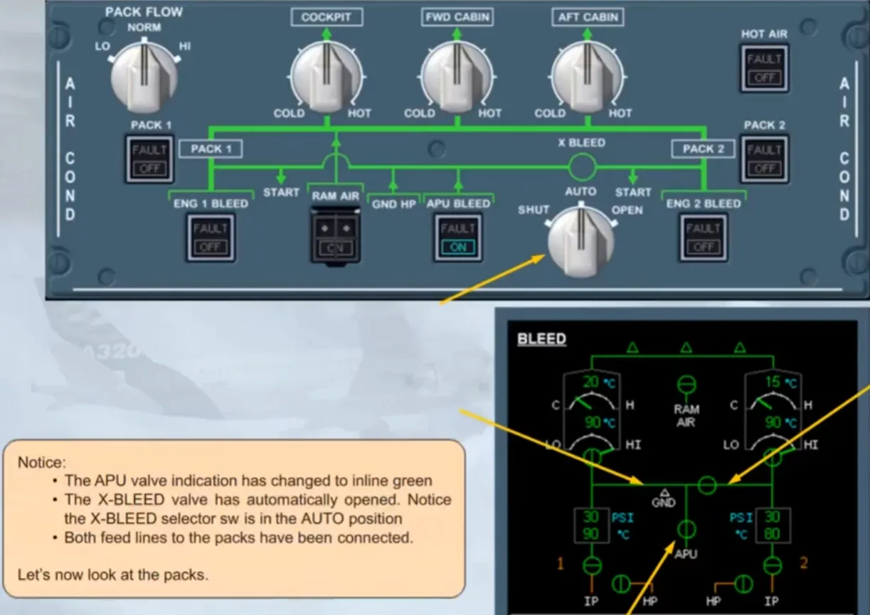
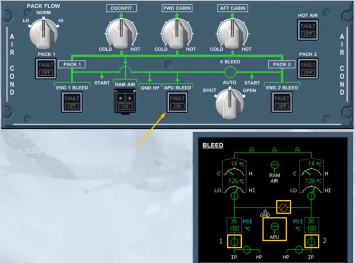
It is now time to get some air to the packs. As the APU is already running, we will set the APU BLEED pb-sw to ON for you. That allows you to watch the ECAM indications.
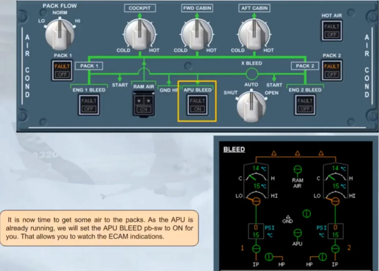
Notice:
- The APU valve indication has changed to inline green
- The X-BLEED valve has automatically opened. Notice the X-BLEED selector sw is in the AUTO position
- Both feed lines to the packs have been connected.
Let’s now look at the packs.
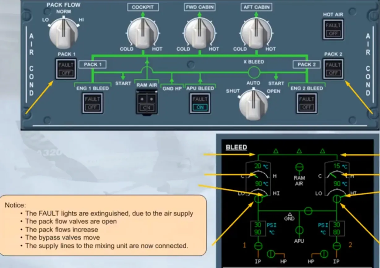
Notice:
- The FAULT lights are extinguished, due to the air supply
- The pack flow valves are open
- The pack flows increase
- The bypass valves move
- The supply lines to the mixing unit are now connected.
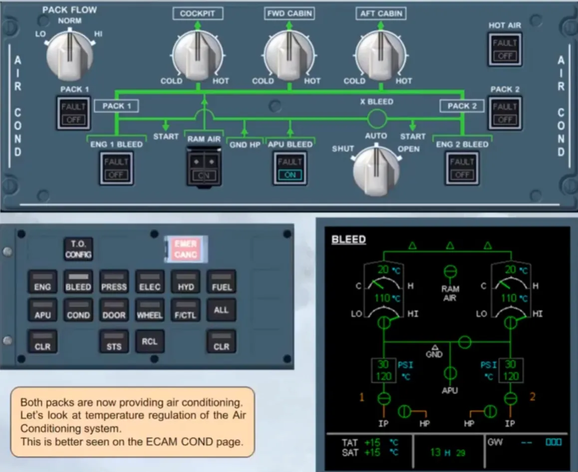
Both packs are now providing air conditioning. Let’s look at temperature regulation of the Air Conditioning system.
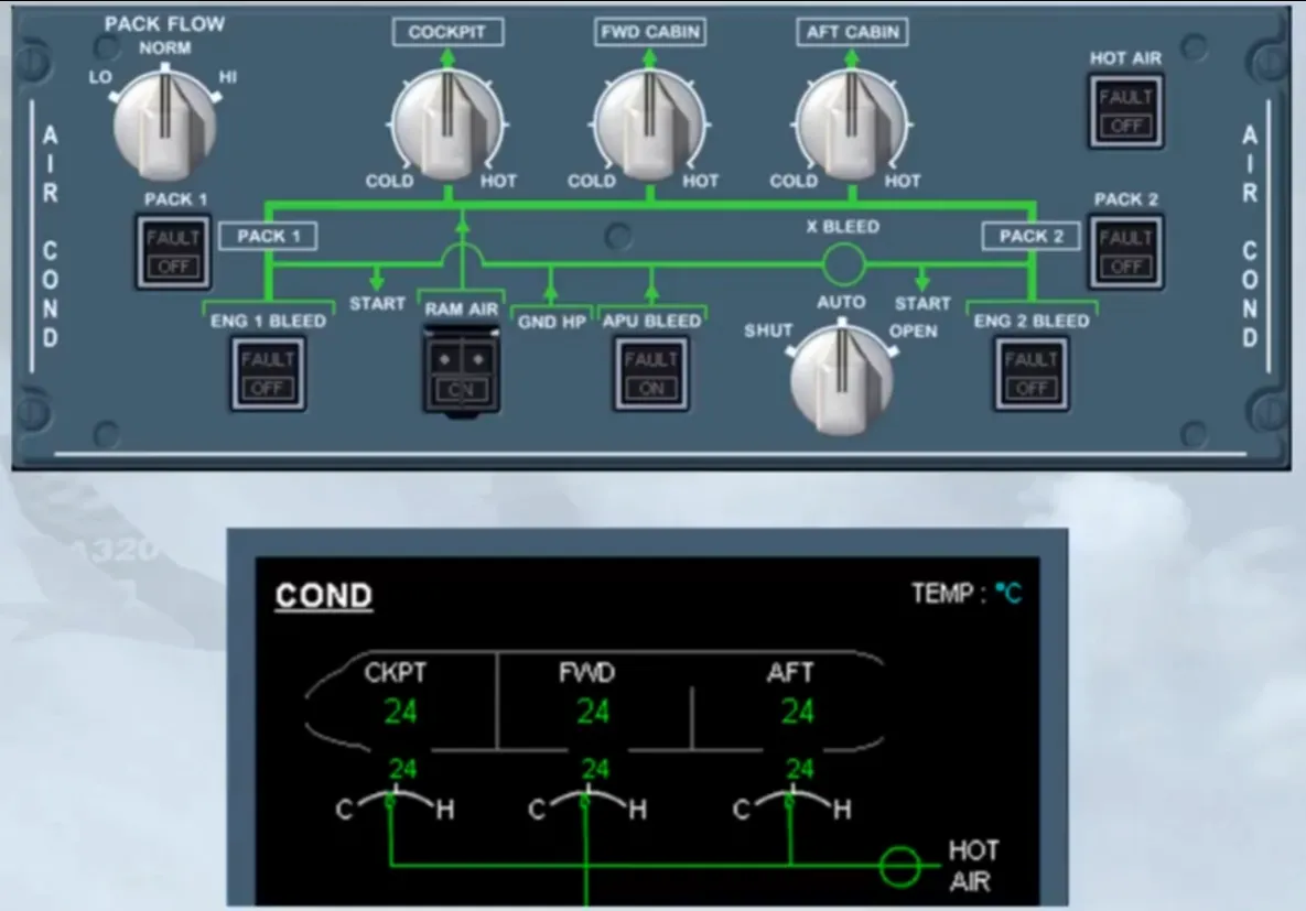
This is better seen on the ECAM COND page.
Let us concentrate on the upper part of the ECAM COND page.
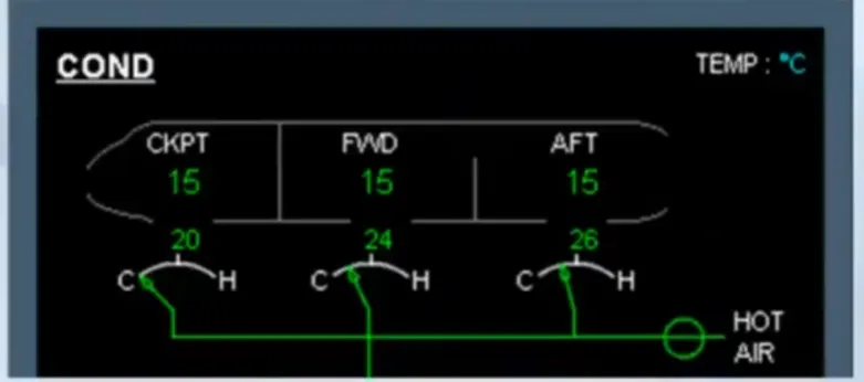
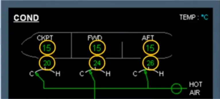
Look carefully at the indications, notice in particular:
- The zone temperatures
- The duct inlet temperatures.
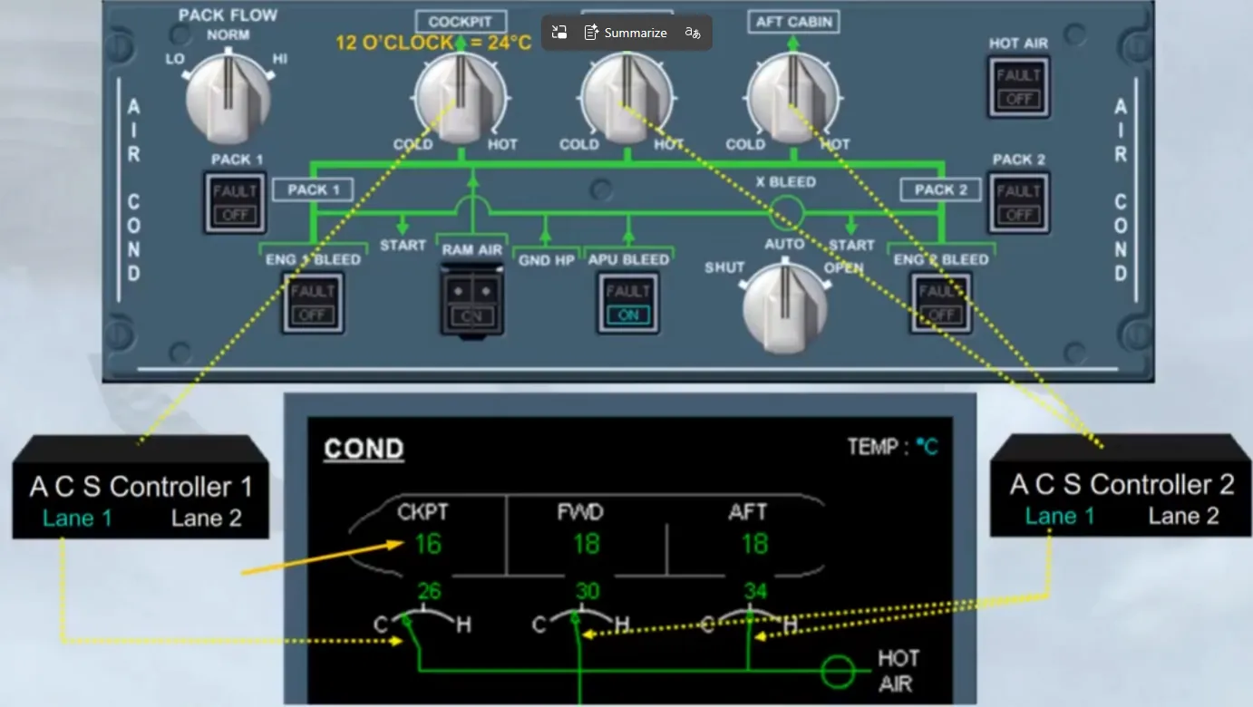
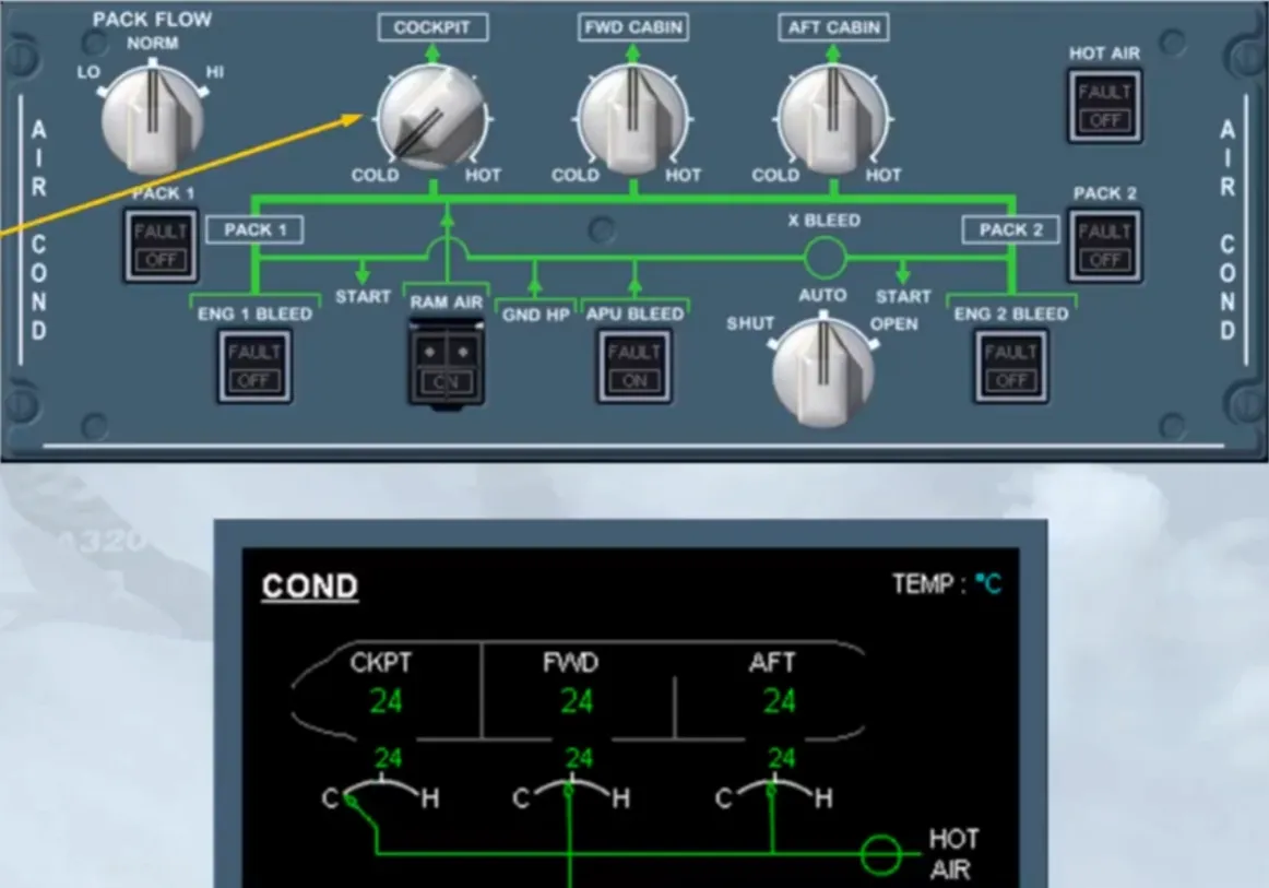
Temperature regulation is achieved the same way for all zones. We will demonstrate the concept using the cockpit zone as an example。
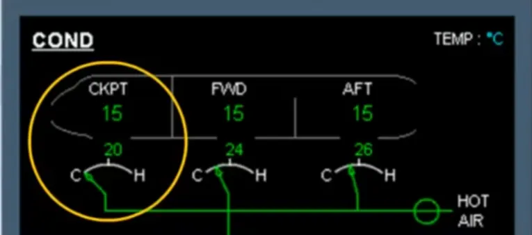
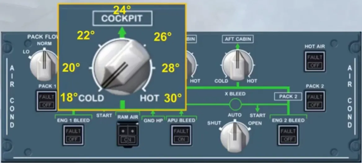
The cockpit zone temperature selector is in the 12 o’clock position.
In this position, a zone temperature of approximately 24° C is asked.
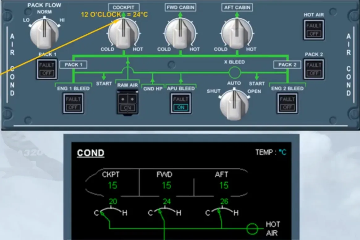
As the 15° C of the cockpit zone is well below 24°, the related ACS Controller sends a command to increase the amount of hot air to be added. Note:
- The cockpit TRIM AIR valve is controlled by the active lane of the ACS Controller 1
- The FWD and AFT TRIM AIR valves are controlled by the active lane of the ACS Controller 2.
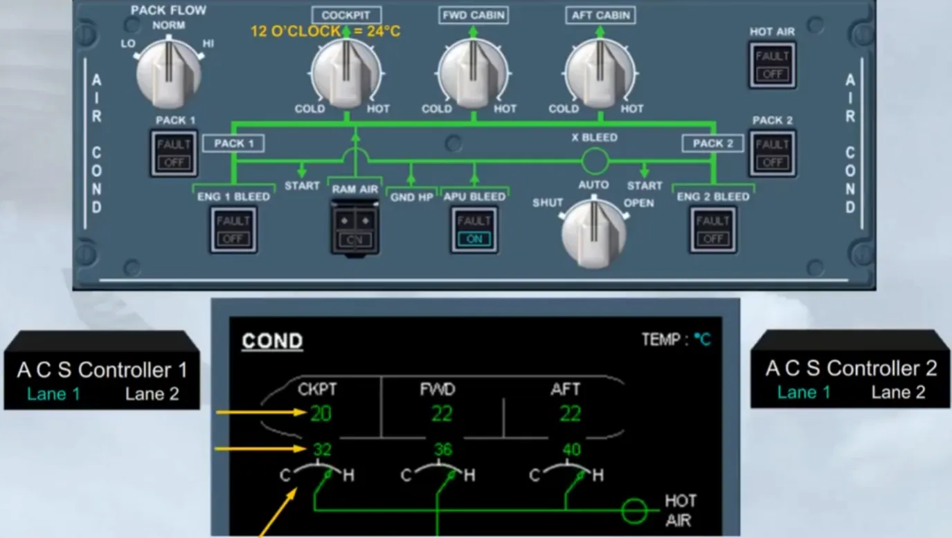
Due to this command:
- The trim air valve opens
- The zone duct temperature increases and so, warm air is supplied to the cockpit zone
- The cockpit zone starts to warm up.
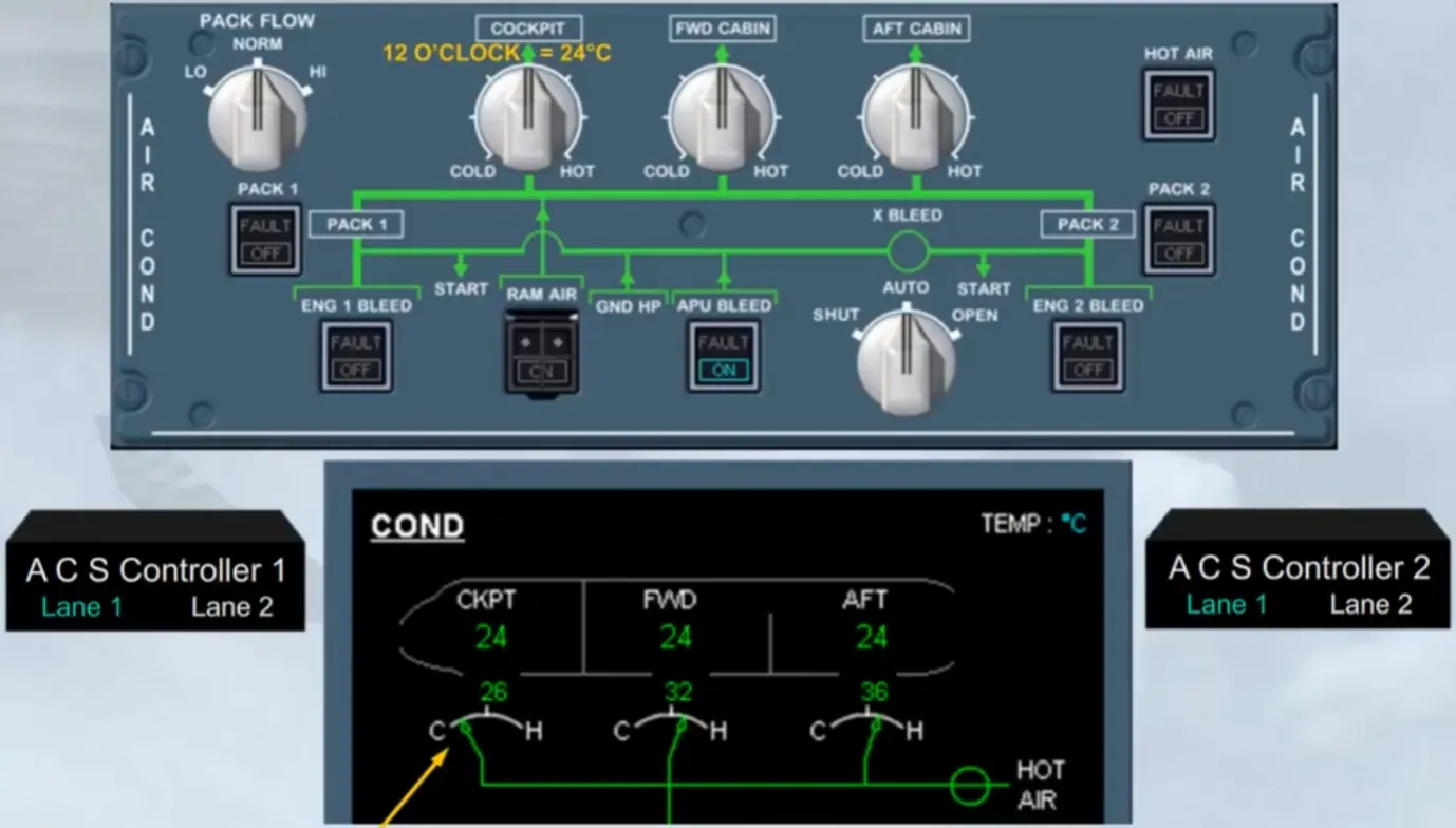
Once the cockpit zone reaches the demanded temperature the trim air valve will move, reducing the amount of hot air, and then will move as required to maintain the zone temperature.
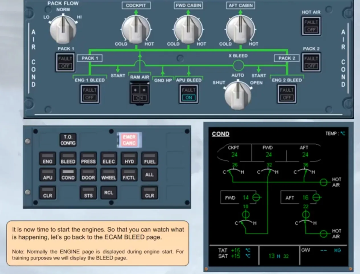
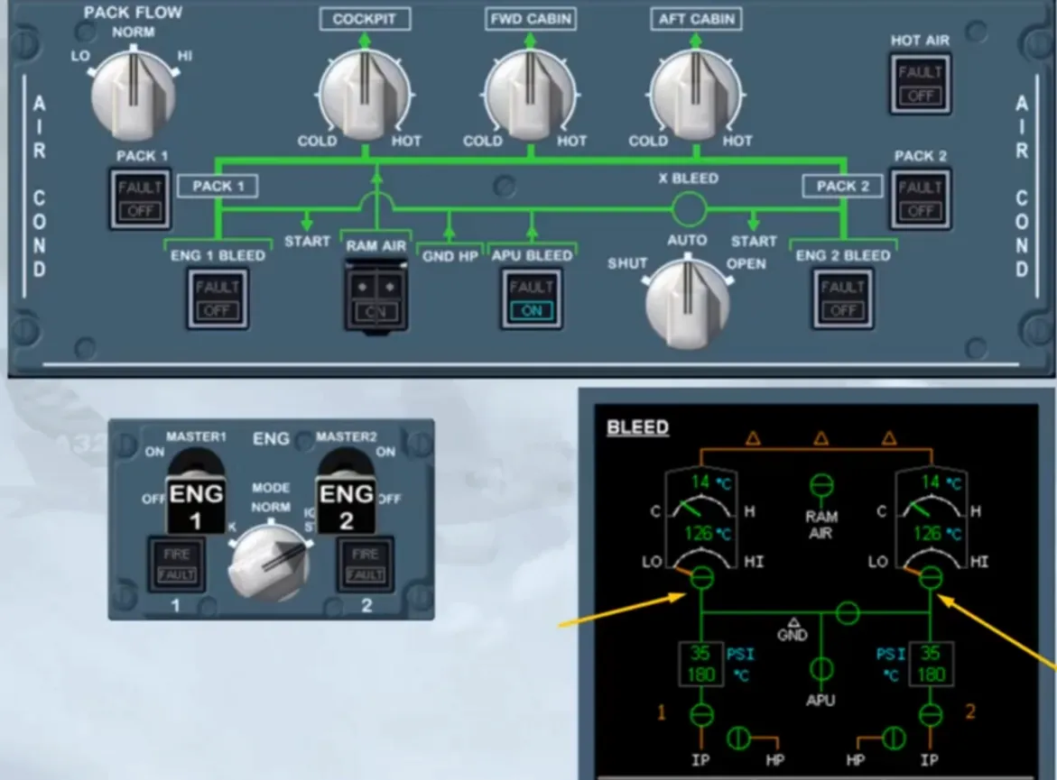
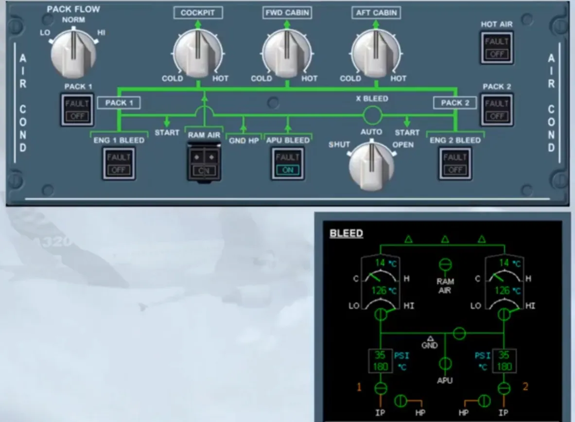
It is now time to start the engines. So that you can watch what is happening, let’s go back to the ECAM BLEED page.
Note: Normally the ENGINE page is displayed during engine start. For training purposes we will display the BLEED page.
As soon as the ENG MODE selector is set to IGN/START, the pack valves close. This is so that all of the APU bleed air can be used tostart the engines.
Note: if it takes more than 30 seconds to set the ENG MASTER switch to ON, the pack valves re open. They will close again when the ENG MASTER switch is set to ON.
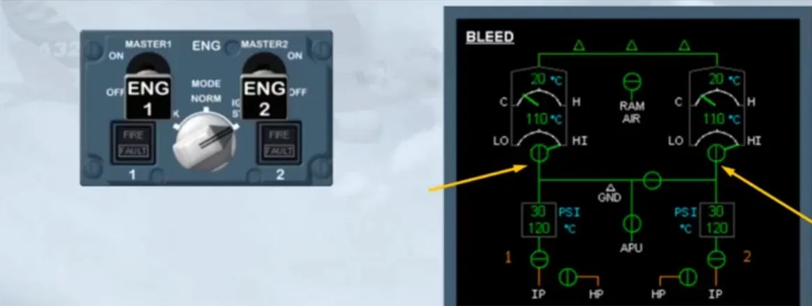
30 seconds after the engine starting sequence is completed or when the ENG MODE sel is set back to NORM:
- The pack valves open
- The APU bleed supplies the packs.

Notice that the engine bleed valves are closed, even with both engines running. This is because APU bleed has priority over the engine bleed. So, if you were departing from a performance limited runway, the packs could run from the APU bleed air, resulting in no loss of engine performance (no weight penalty).
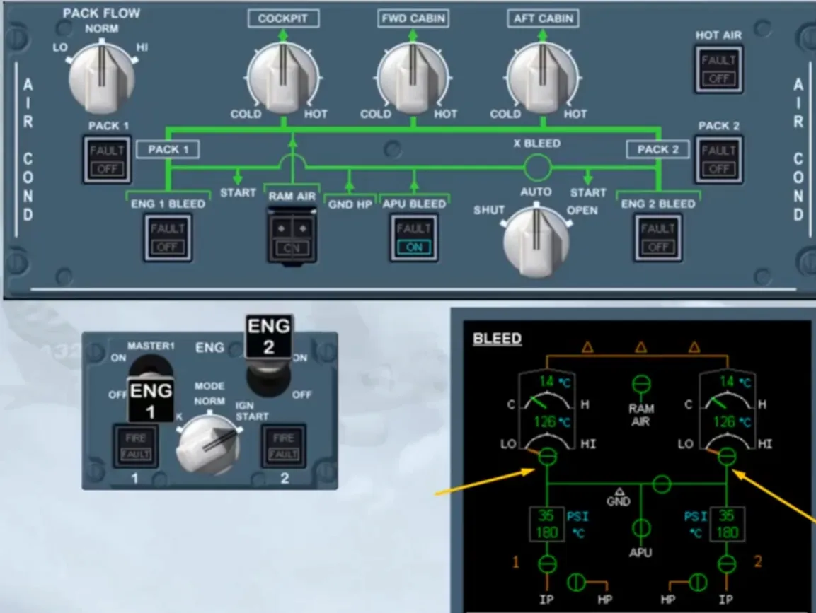
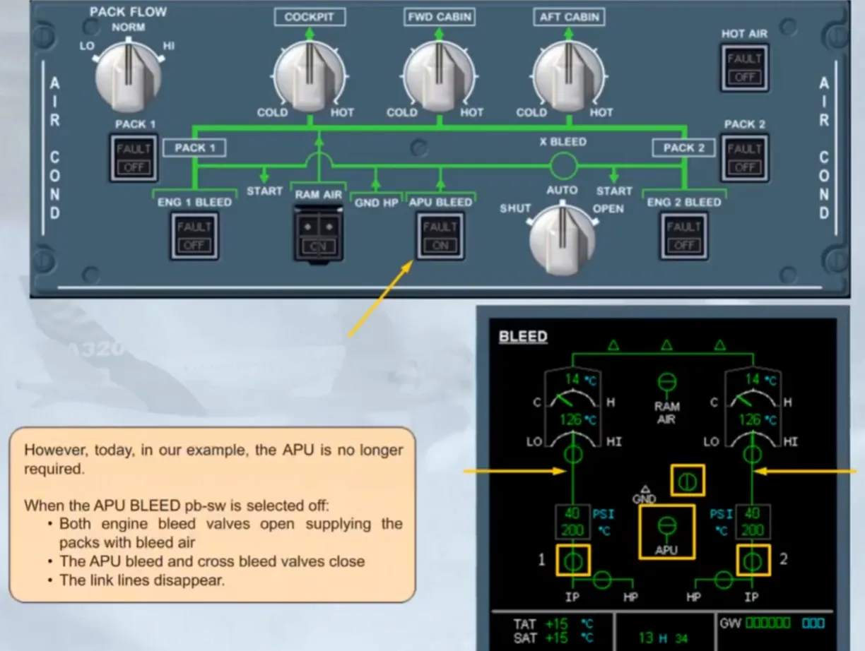
However, today, in our example, the APU is no longer required.
When the APU BLEED pb-sw is selected off:
- Both engine bleed valves open supplying the packs with bleed air
- The APU bleed and cross bleed valves close
- The link lines disappear.
Notice that the pack flow reduces. This is because the engines provide a higher flow rate than the APU. Also note that the air conditioning control panel is now in a normal lights out configuration.
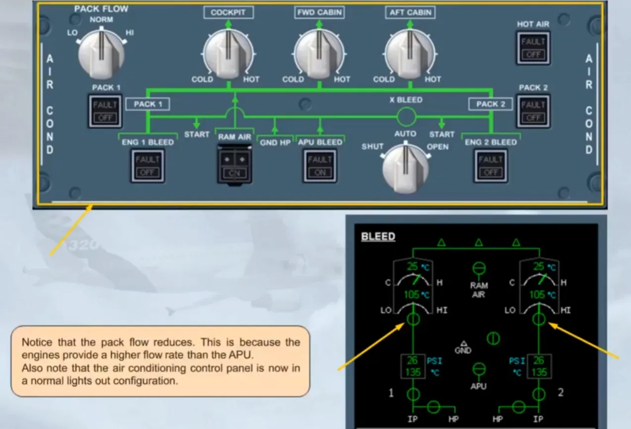
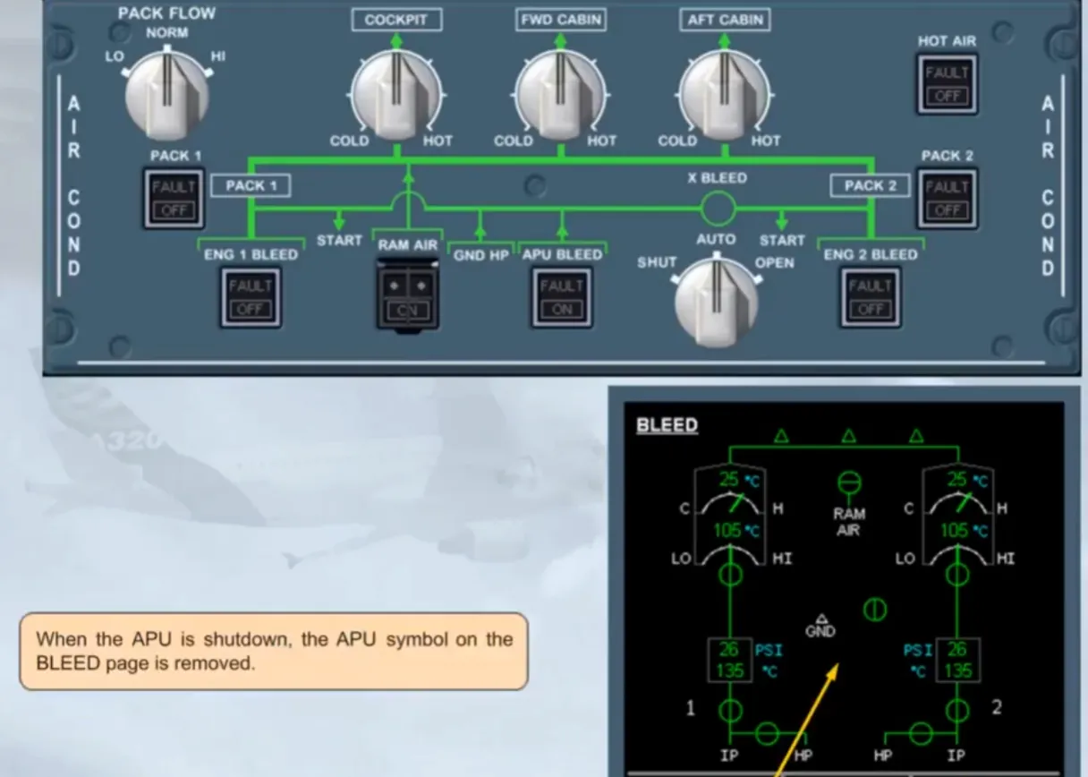
When the APU is shutdown, the APU symbol on the BLEED page is removed.
During the flight phase, the air conditioning system will work automatically. The pilot just has to adjust zone temperature. Let us assume that you wish to cool down the cockpit, by turning the cockpit zone selector.
We have set a cockpit zone temperature of 18 degrees. Because a lowtemperature has been asked, the trim air valve will close, and the cool pack output will supply the cockpit zone.
Note that each increment on the zone temperature sel scale is 2 degrees which gives a selectable range from 18 degrees at COLD to 30 degrees at HOT.
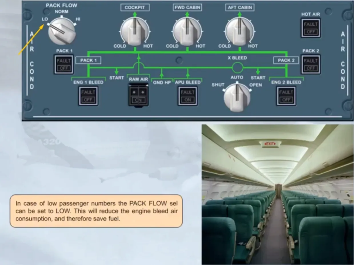
In case of low passenger numbers the PACK FLOW sel can be set to LOW. This will reduce the engine bleed air consumption, and therefore save fuel.
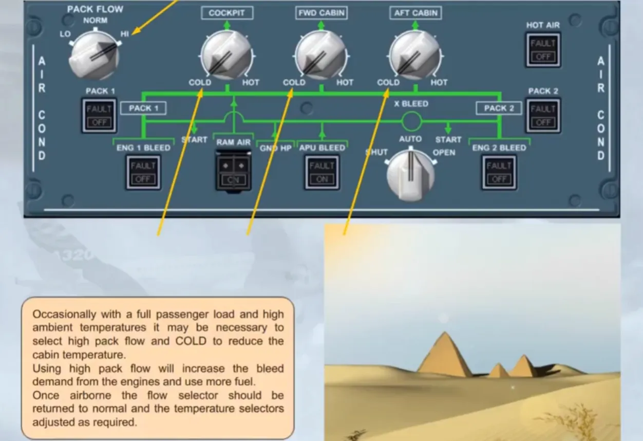
Occasionally with a full passenger load and high ambient temperatures it may be necessary to select high pack flow and COLD to reduce the cabin temperature.
Using high pack flow will increase the bleed demand from the engines and use more fuel.
Once airborne the flow selector should bereturned to normal and the temperature selectors adjusted as required.
After landing and engine shutdown, the system can be set to run from the APU or switched off completely.
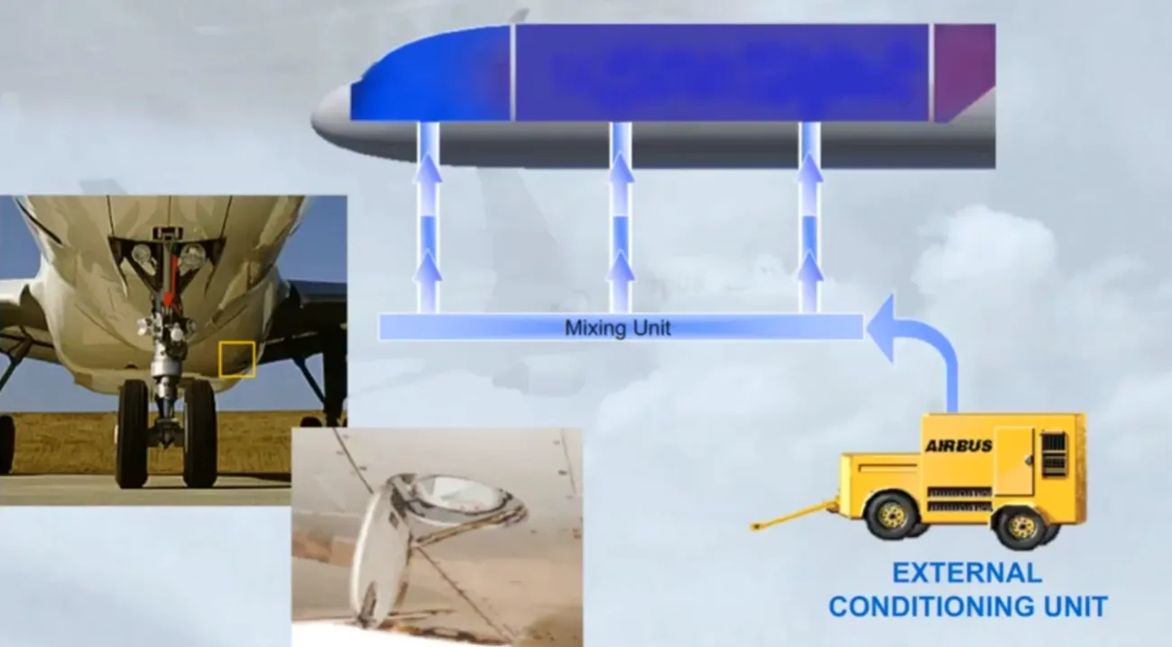
An exteral conditioning unit can also be connected via a low pressure connection point on the underside of the aircraft. The low pressure air is fed to the mixing unit and then into the three zones.
There are no indications in the cockpit to show that an external conditioning unit is in use.
Module completed
Video study
Section titled “Video study”- Watch the video available on YouTube