Penumatic System
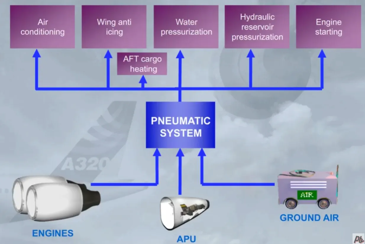
The A320 pneumatic system supplies high pressure hot air for:
- Air conditioning
- Wing anti icing
- Water pressurization
- Hydraulic reservoir pressurization
- Engine starting
- If installed, the AFT cargo heating.
High pressure hot air can be supplied from three sources:
- The engine bleed system
- The APU
- An external high pressure ground power unit
Note: Wing Anti Icing is not permitted when the pneumatic system is supplied by the APU Bleed.
The pneumatic system is controlled and monitored by 2 Bleed Monitoring Computers (BMCs). There is one BMC for each engine bleed system. Both BMCs are interconnected and if one fails, the other takes over most of its functions.
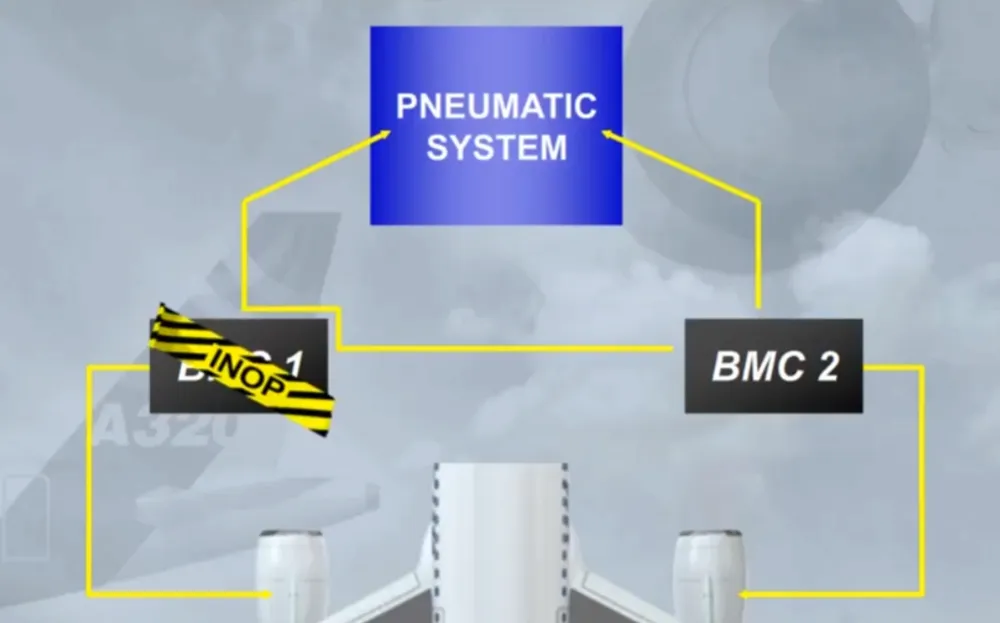
An ambient overheat, in the vicinity of the hot air ducts in the fuselage, wings and pylons, will be detected by air leakage detection loops.
If a leak is detected, a signal is sent to the BMCs which automatically isolate the affected area.

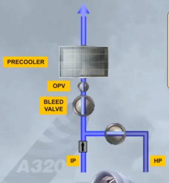
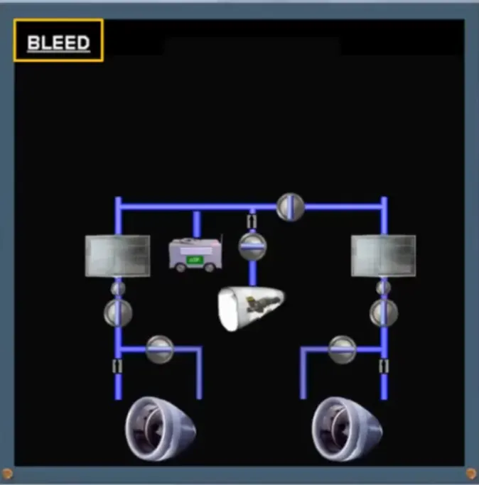
In flight, the primary source for high pressure air is the engines. Both engines have similar bleed systems.
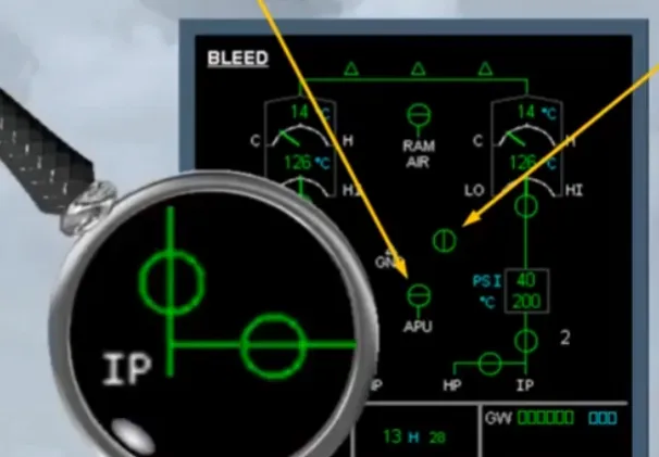
Air is bled from two compressor stages of the engine, the Intermediate Pressure (IP) port and the High Pressure (HP) port.

There is a HP valve which can cut off bleed air from the HP port.
It is automatically controlled by the system and it will limit the downstream pressure.
Note: There is a non return valve at the IP to protect the compressor against a reverse flow from the HP.
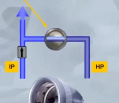
The High Pressure section (HP) is only used whenthere is insufficient pressure from the Intermediate Pressure output(IP), due to a low engine compressor speed. Once the engine compressor speed is high enough, the IP is sufficient and the HP valve closes.
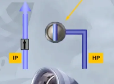
The air extracted from the compressor then goes to ableed valve which acts as a shut off and pressure regulating valve.
Since the temperature of the bleed air is high, it passes through a precooler before being distributed to the users.
The precooler heat exchanger uses cooling air bled from the engine fan to regulate the temperature according to the demand.
Note: An Over Pressure Valve (OPV) will automatically close in case of pressure regulation problem.
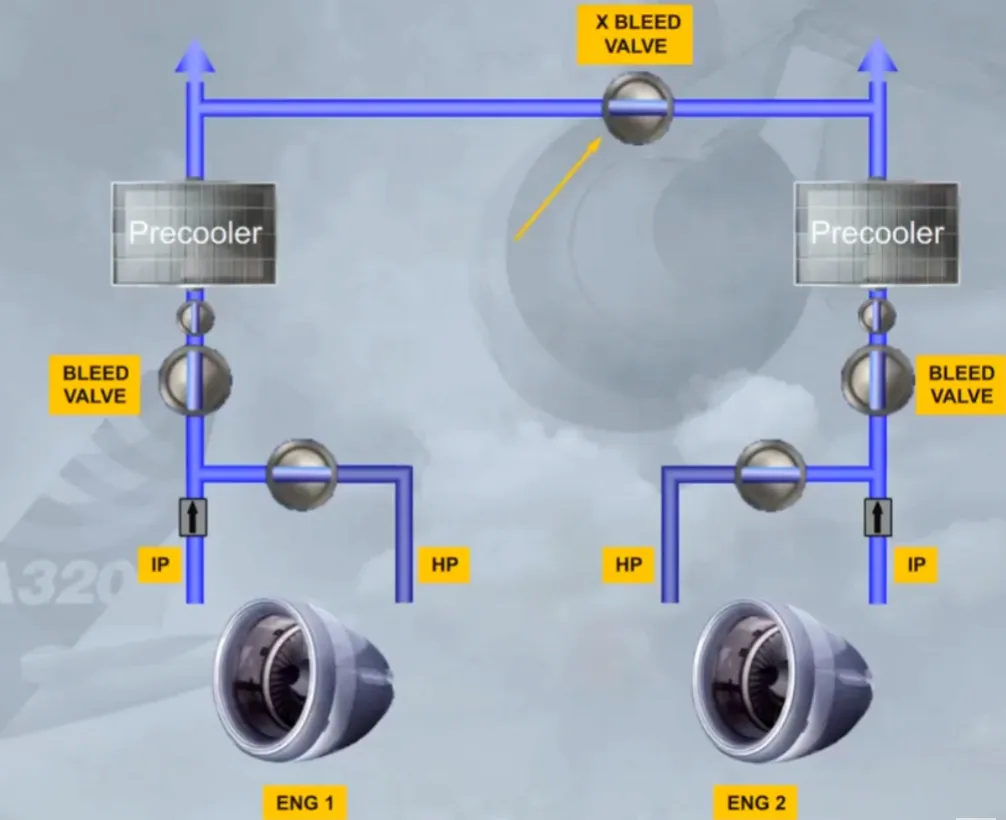
ENG 2 has an identical BLEED SYSTEM.
Both systems are connected by a crossbleed duct.
A crossbleed valve permits their interconnection or isolation.
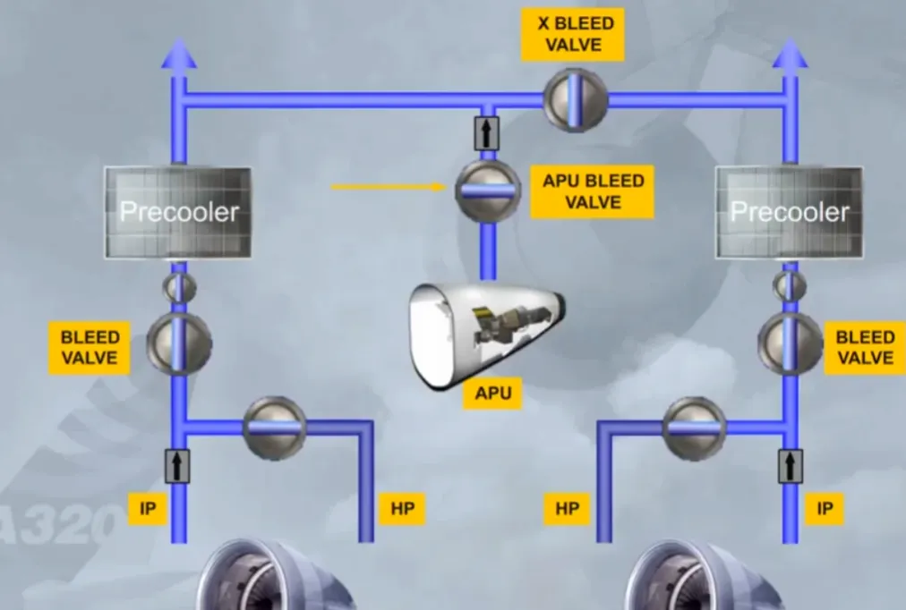
The APU can also be used for BLEED air supply. This is usually done on ground for air conditioning and for engine start. However, APU BLEED air is also available in flight.
APU BLEED air is controlled by the APU bleed valve which operates as a shut off valve.
Note: A non return valve, protects the APU compressor against a reverse flow from another supply source.
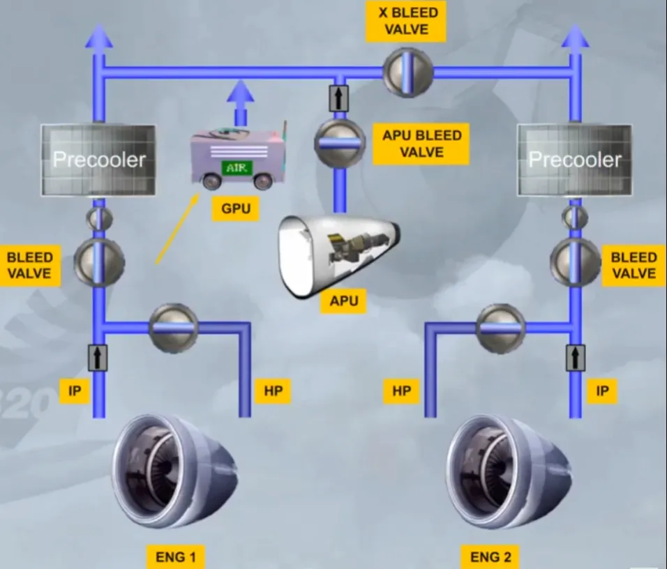
Should the APU not be available, a high pressure ground power unit can be connected.
This completes the pneumatic system. We will now show you how system information is displayed to the pilots.
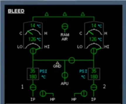
Information on the pneumatic system is displayed on the lower part of the ECAM BLEED page.
Note: We have shaded the upper part of the ECAM BLEED page because it is related to the AIR CONDITIONING chapter. This will be covered in a later module.
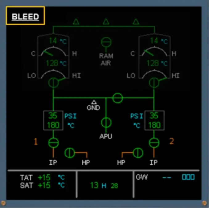
Let’s identify the system components on the ECAM page now:
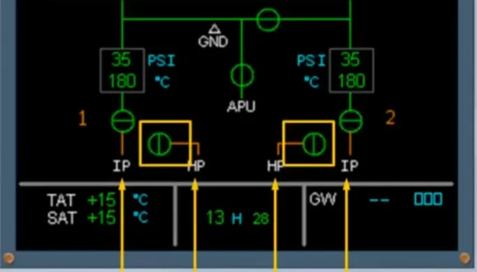
- The IP and HP ports
- The HP valves…
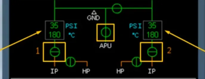
- The engine bleed valves
- The precoolers
- The APU BLEED valve, only when APU is running…
- The crossbleed valve
- The high pressure ground indication, always displayed on ground even if the ground unit is not connected.
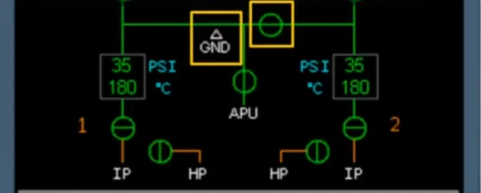
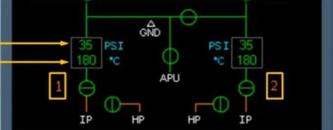
The following information is also displayed:
- Precooler inlet, air pressure
- Precooler outlet, air temperature
- Engine identification numbers.
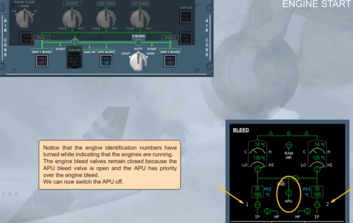
Controls for the pneumatic system are part of the AIR COND panel, located on the overhead panel.
Again, we have shaded the controls which belong to the AIR CONDITIONING chapter.
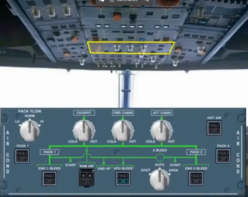
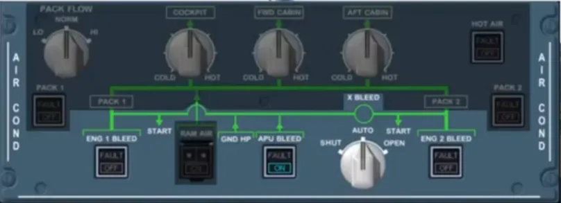
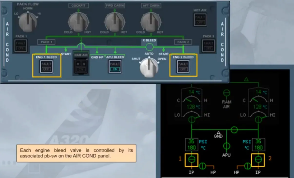
Each engine bleed valve is controlled by its associated pb-sw on the AIR COND panel.
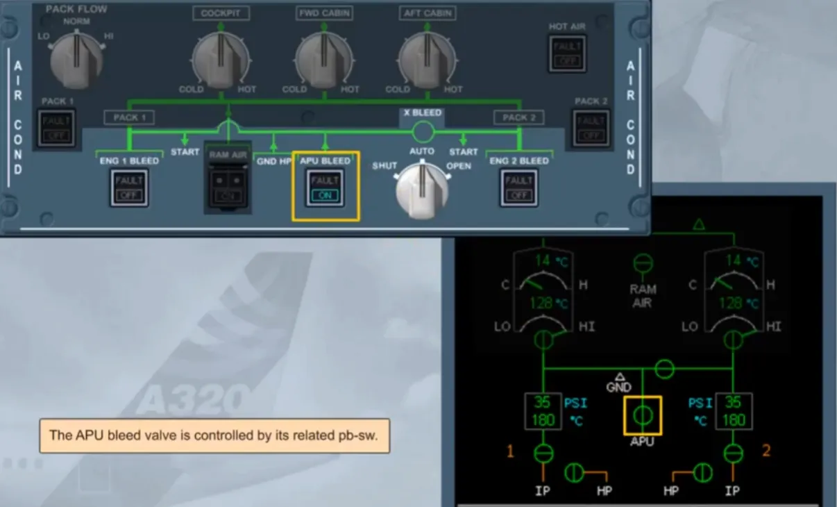
The APU bleed valve is controlled by its related pb-sw.
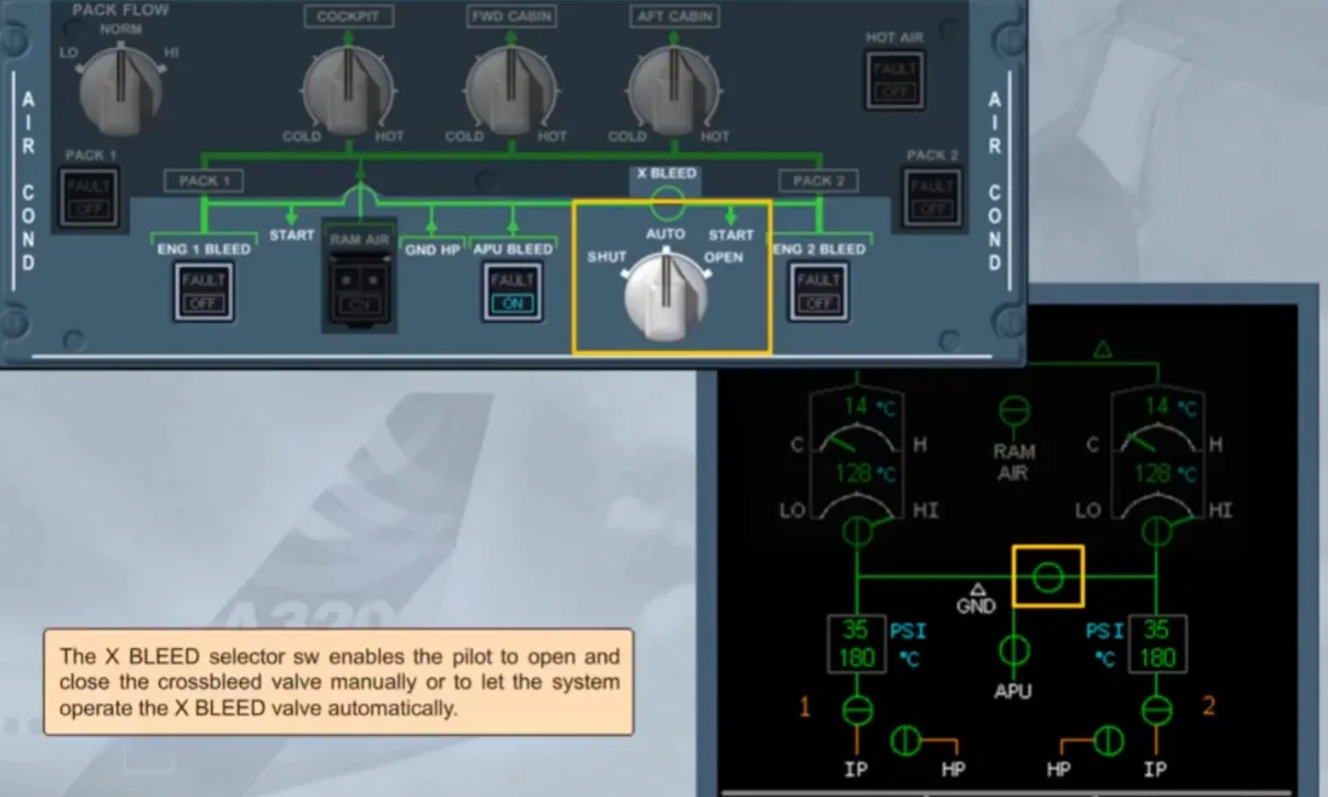
The X BLEED selector sw enables the pilot to open and close the crossbleed valve manually or to let the system operate the X BLEED valve automatically.
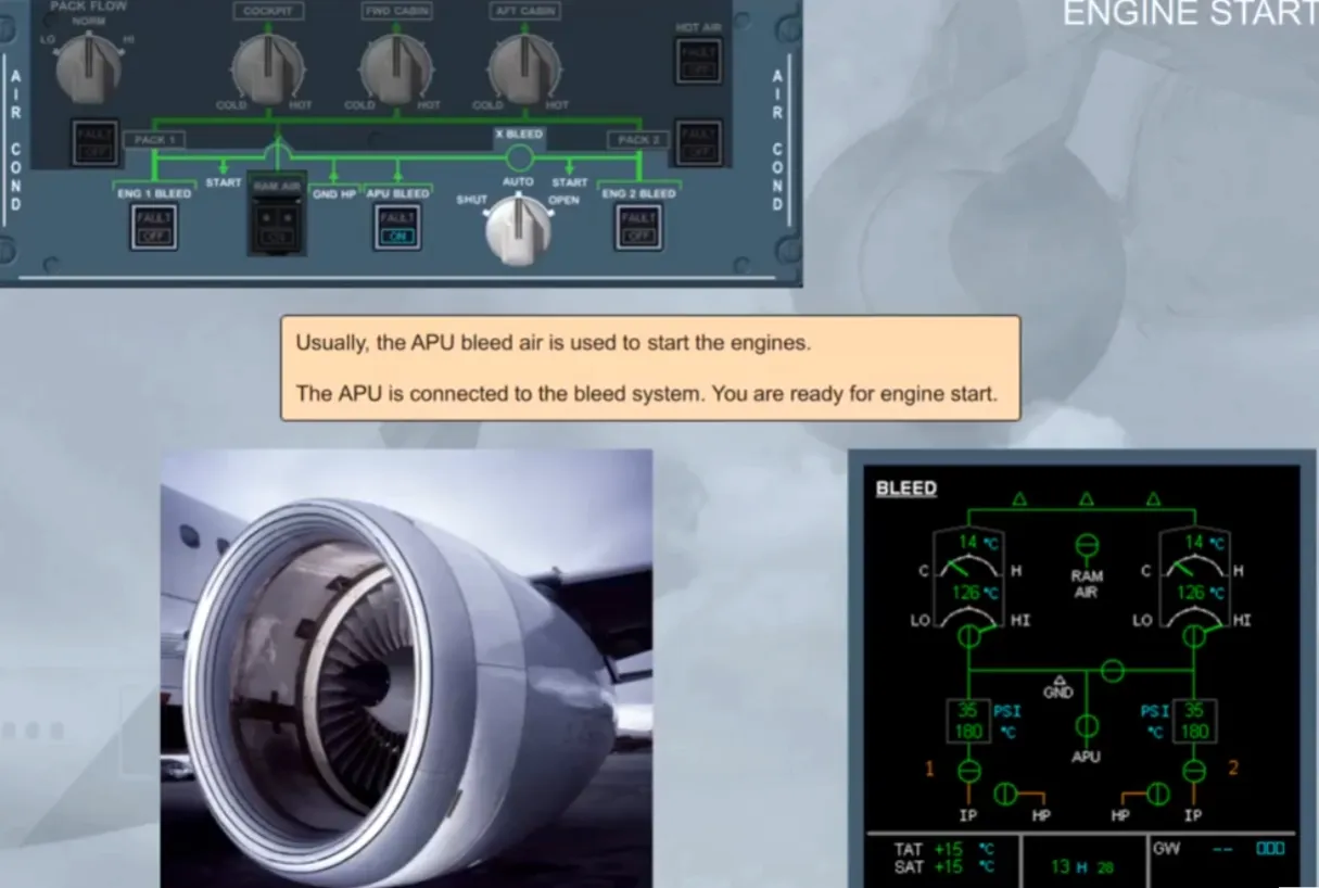
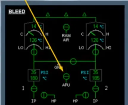
Usually, the APU bleed air is used to start the engines.
The APU is connected to the bleed system. You are ready for engine start.
Notice that the engine identification numbers have turned white indicating that the engines are running. The engine bleed valves remain closed because the APU bleed valve is open and the APU has priority over the engine bleed. We can now switch the APU off.
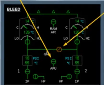
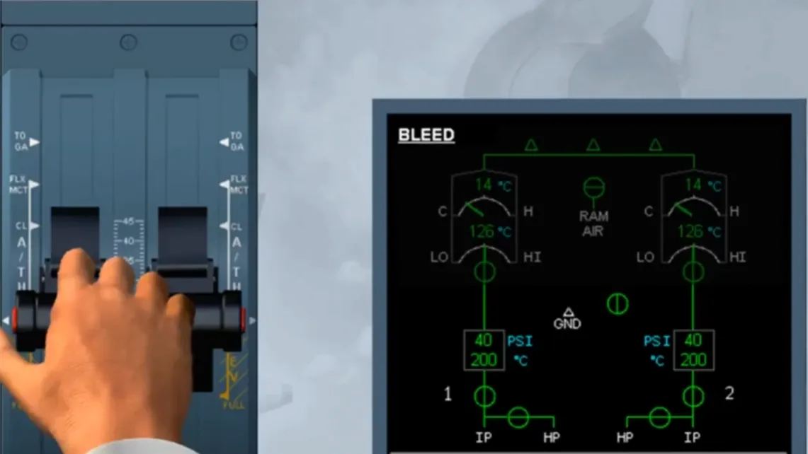
Observe the ECAM:
- The APU BLEED valve is closed
- The X-BLEED valve is automatically closed. It is displayed amber during transit
- The ENGINE BLEED valves and HP valves are displayed in-line green because they have been automatically opened.
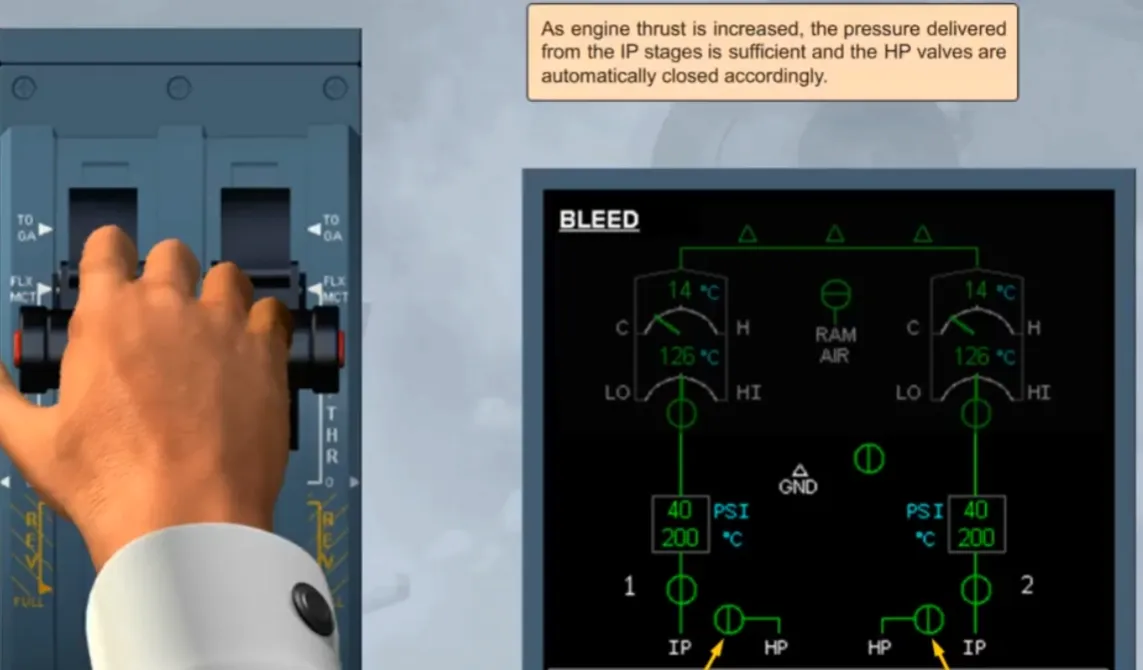
We will now talk about the changes that occur in the pneumatic system during take off.
Note: Normally, the ECAM ENGINE page is displayed for takeoff. For training purposes, we will display the ECAM BLEED page.
As engine thrust is increased, the pressure delivered from the IP stages is sufficient and the HP valves are automatically closed accordingly.
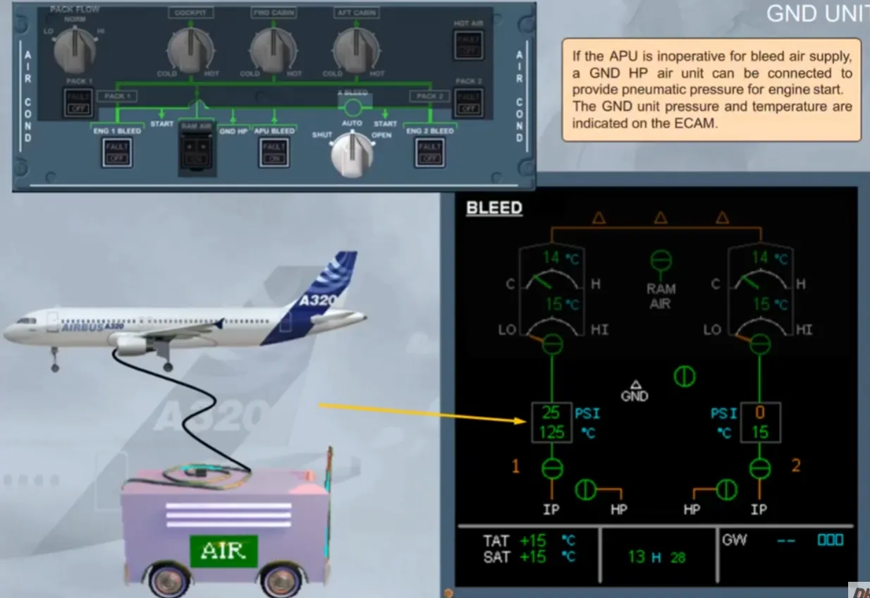
If the APU is inoperative for bleed air supply, a GND HP air unit can be connected to provide pneumatic pressure for engine start.The GND unit pressure and temperature are indicated on the ECAM.
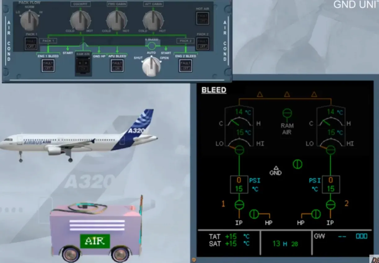
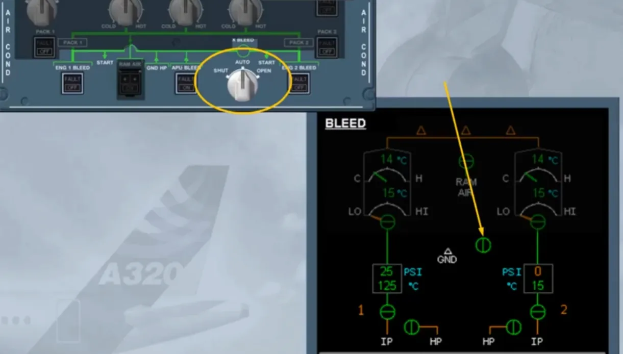
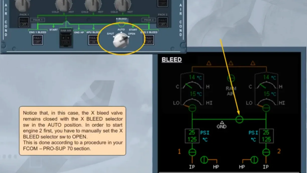
Notice that, in this case, the X bleed valveremains closed with the X BLEED selector sw in the AUTO position. In order to start engine 2 first, you have to manually set the XBLEED selector sw to OPEN. This is done according to a procedure in your FCOM-PRO-SUP 70 section.
Module completed
Video study
Section titled “Video study”- Watch the video available on YouTube