Fuel System
The A320 fuel system is much like a conventional jet aircraft fuel system.
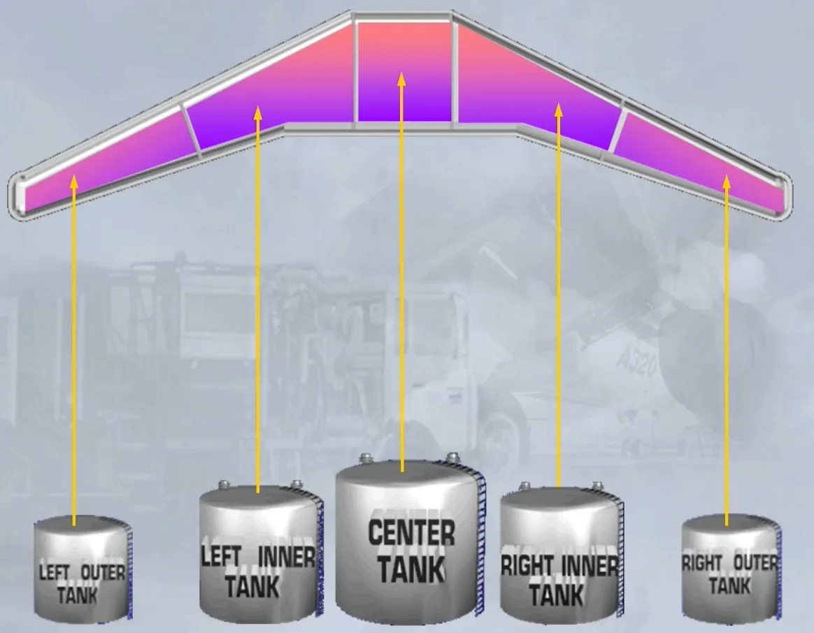
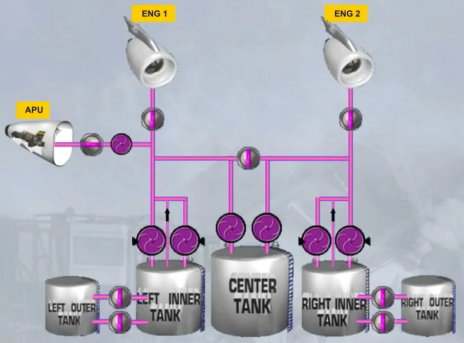
It has fuel tanks located:
- In the center fuselage
- In the wings.
The center tank is located in the fuselage.
The inner and outer tanks are located in the wings.
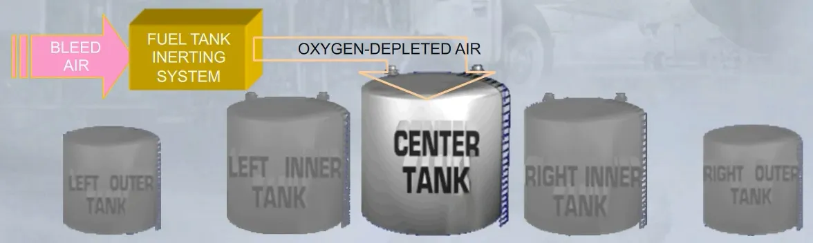
A fuel tank inerting system is installed in the belly fairing of the aircraft for the fuel center tank as it is the only one that has a high flammability exposure.
The system produces an oxygen-depleted air (with less than 12% of oxygen) that goes in this tank to replace the ambient air. This is obtained by extracting some engine bleed air and through an air separation module by taping the nitrogen molecules.
Note: The fuel tank inerting system works independently as soon as the engines start and until they stop, and does not require any flight crew action.
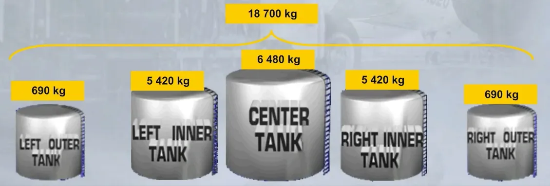
The total usable fuel quantity is around 18700 kg (standard density).
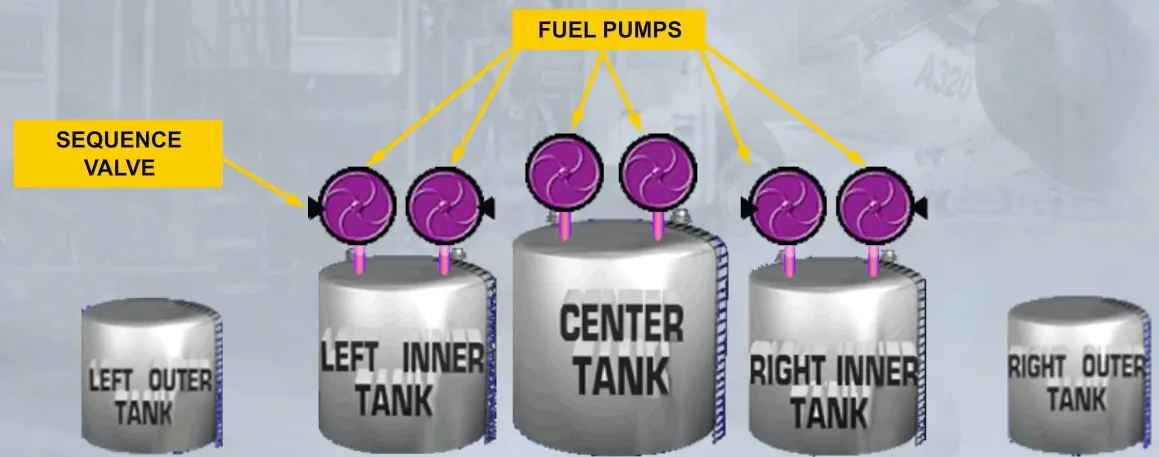
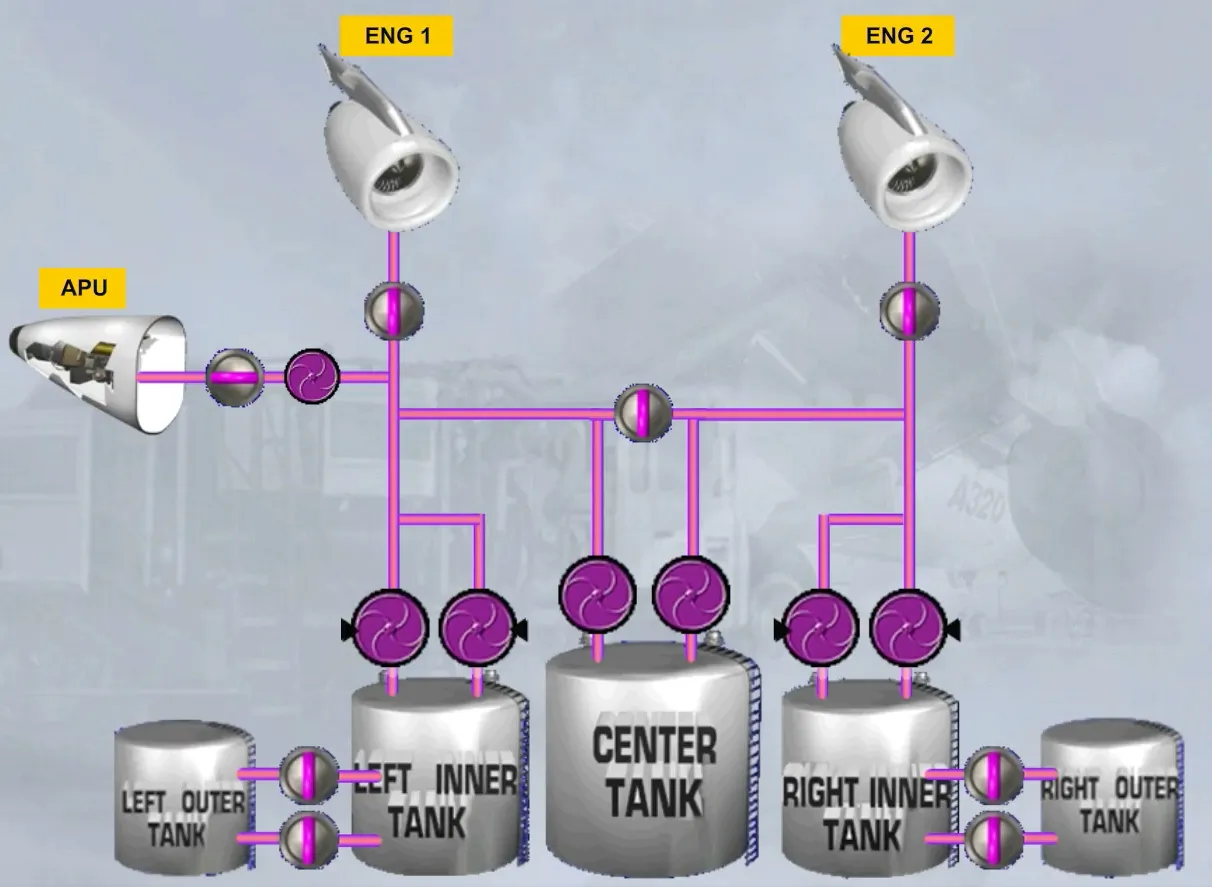
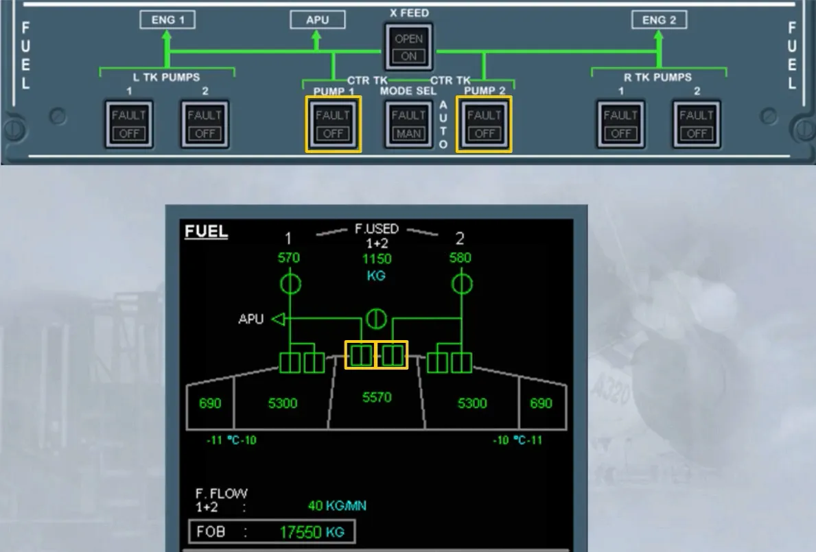
Two fuel pumps are installed in the center tank and two fuel pumps are installed in each inner tank.
Note: Each inner tank pump has a sequence valve which allows to permit the fuel delivery preferentially from the center tank pumps, each time the center tank pumps and the inner tank pumps are running together.
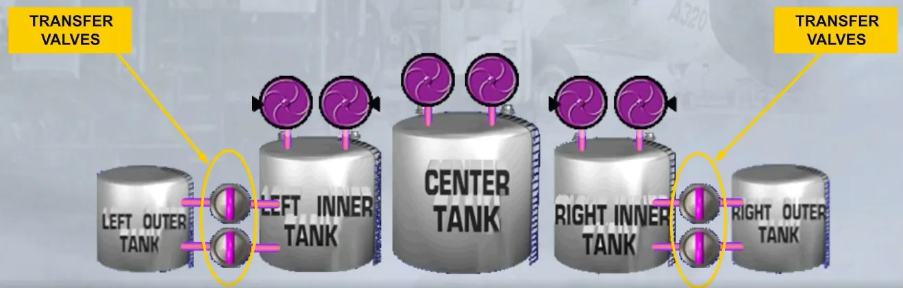
There are two transfer valves in each wing.
They transfer fuel from the outer tanks to the inner tanks.
When the pumps are running, the center tank or the inner tanks feed their respective engine.
The fuel flow to each engine can be stopped by closing its respective Low Pressure (LP) valve via:
- The ENG MASTER sw, or
- The ENG FIRE pb.

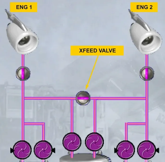
There is a cross feed valve which allows when it is open:
- Both engines to be fed from one side, or
- One engine to be fed from both sides.
Note: One pump is capable to supply both engines.
The left part of fuel system feeds the APU.
A LP valve is installed to cut off fuel to the APU, when it is not running or an APU FIRE pb is used.
Note: In case of a fuel feed low pressure, the APU will be automatically fed by a special pump.
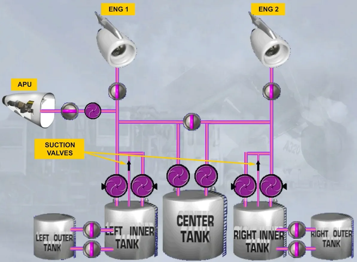
Each engine feeding line from the inner tank is equipped with a suction valve, which allows the related engine to be fed by gravity by only the inner tank.
Note: The gravity feeding from the center tank is not possible.
This represents the basic fuel system.
We will now see how this information is presented to the pilots in the cockpit.
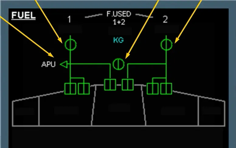
You can see that all the components we have talked about are displayed on the ECAM page.
Let’s briefly review the basic system using the ECAM FUEL page.
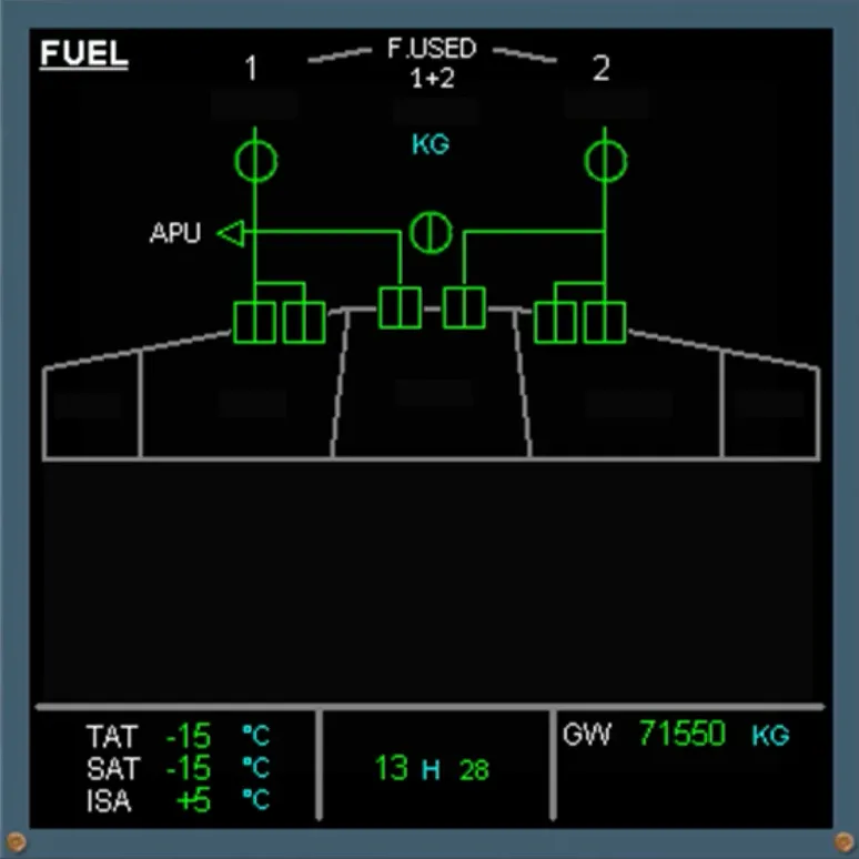
- The center tank in the fuselage
- The inner tanks in the wings
- The outer tanks in the wings …
- The fuel pumps
- The OUTER to INNER transfer indications.
Note: On each side, only one transfer indication shows the two transfer valves, when they are open.
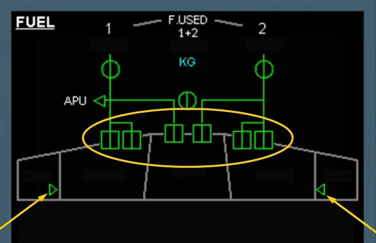
- The engine LP valves
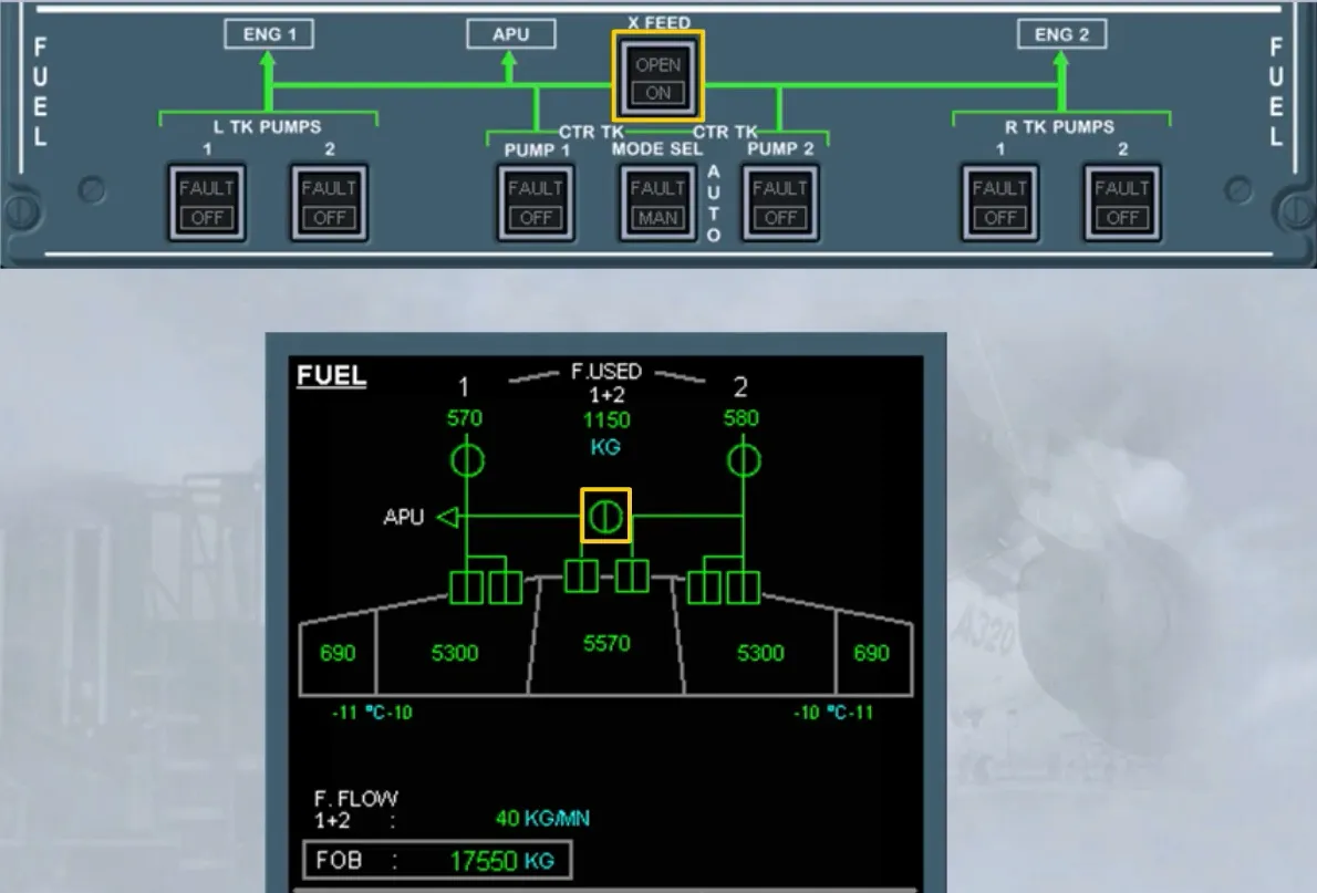
- The crossfeed valve
- The APU LP valve.
Note: The APU fuel pump is not displayed.
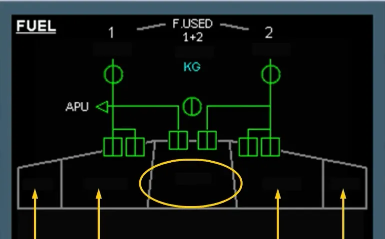
For more clarity, we have left out some indications.
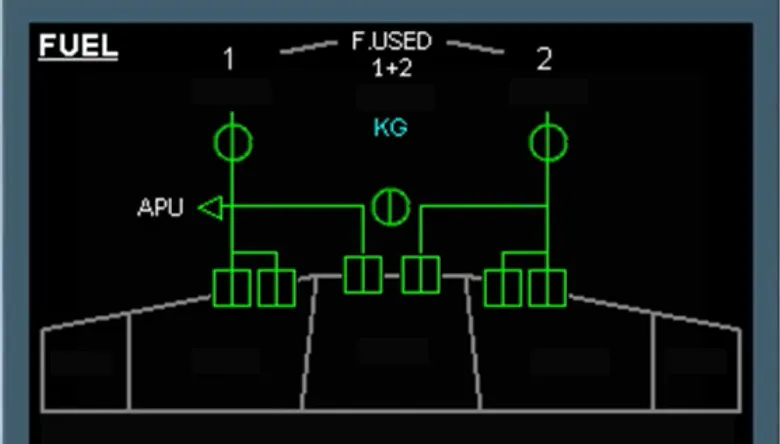
These indications are:
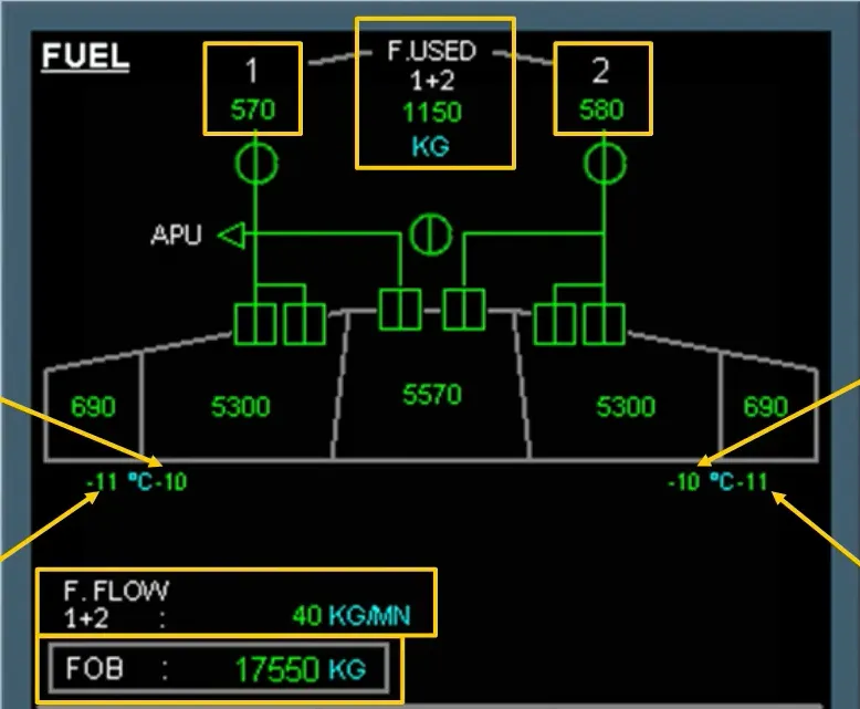
- Outer tank fuel quantity
- Inner tank fuel quantity
- Center tank fuel quantity …
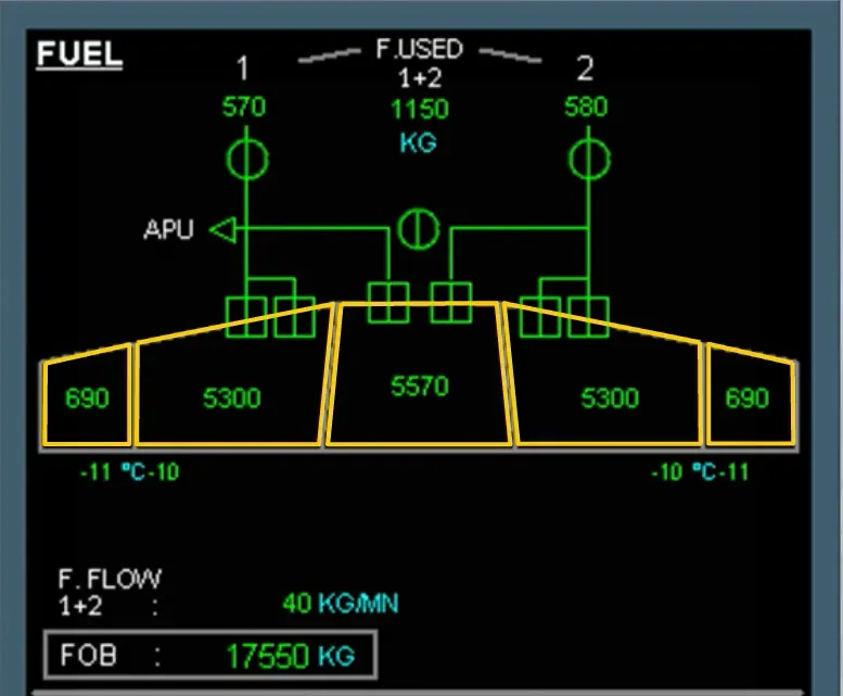
- Fuel on board (FOB)
- Related engine fuel used quantity, with the total fuel used
- Outer tank temperature
- Inner tank temperature.
Note: As an option, the fuel flow can be displayed.
The FUEL panel is located on the overhead panel.
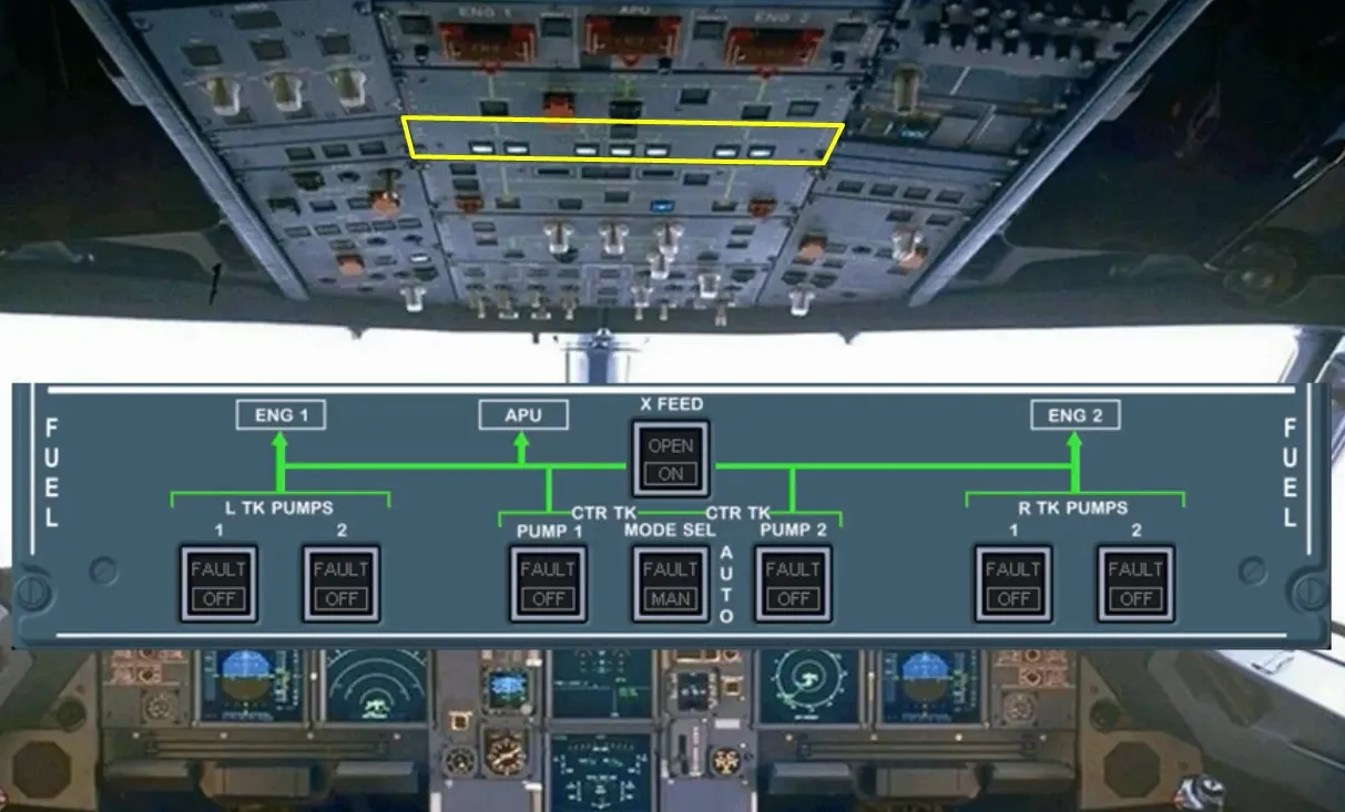
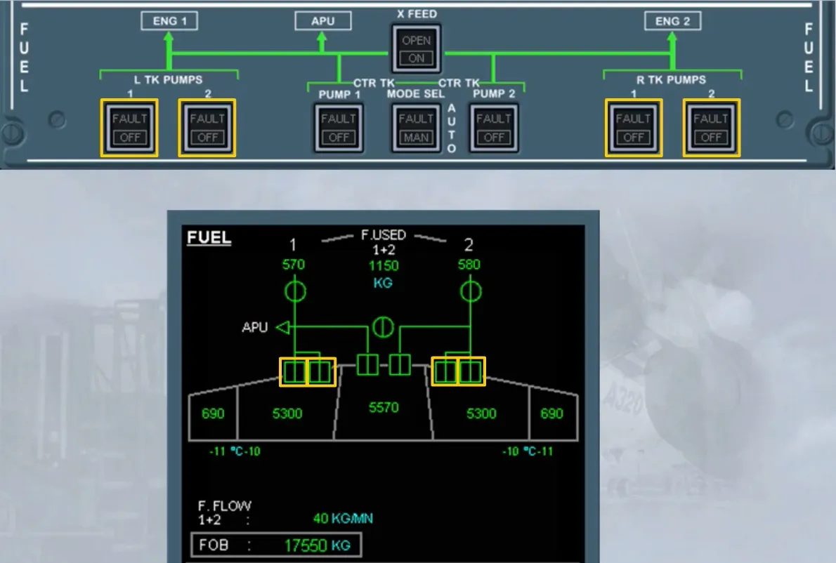
Each wing tank pump is controlled by its related pb-sw on the FUEL panel.
Note: In its light-out position, the related pump is continuously running.
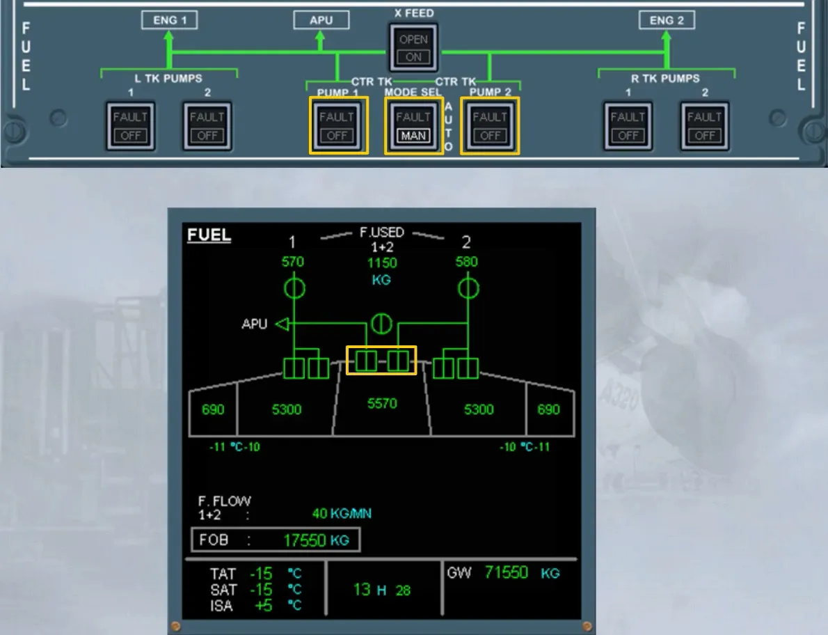
Each center tank pump is controlled by its respective pb-sw.
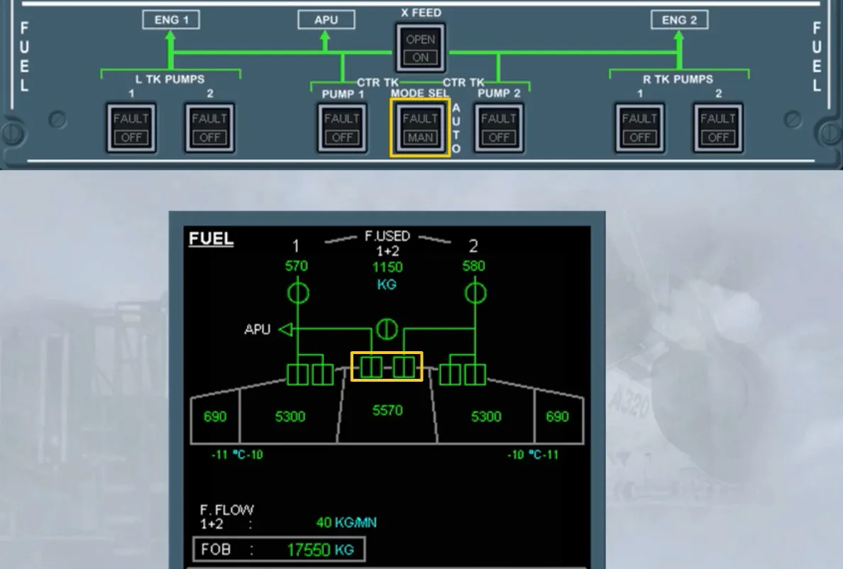
The MODE SEL pb-sw allows the center tank pump to run:
- Automatically:
- At engine start for 2 minutes if slats are extended or
- Continuously if slats are retracted until 5 minutes after the center tank low level is reached.
- Manually:
- The center tank pumps are running, as long as the related pump pb-sw is in light-out position.
The X FEED pb-sw enables the pilot to connect or isolate the left and right sides of the fuel system.
You will find more information in the following modules.
Module Completed