Electrical Failure Cases
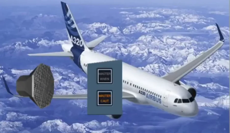
We will now study the electrical emergency configuration.
As there are a lot of events which happen at the same time in the aircraft, we will show these events in a sequential order. Let’s assume we are in flight, and no previous faults have occurred.
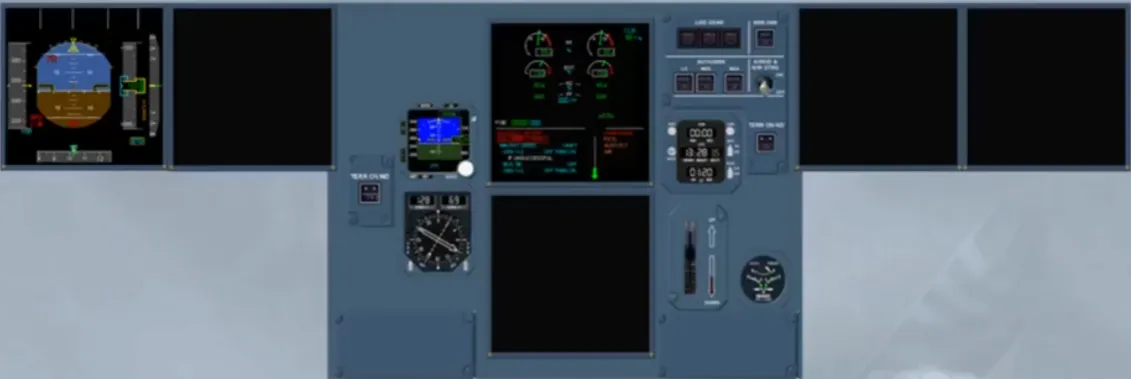
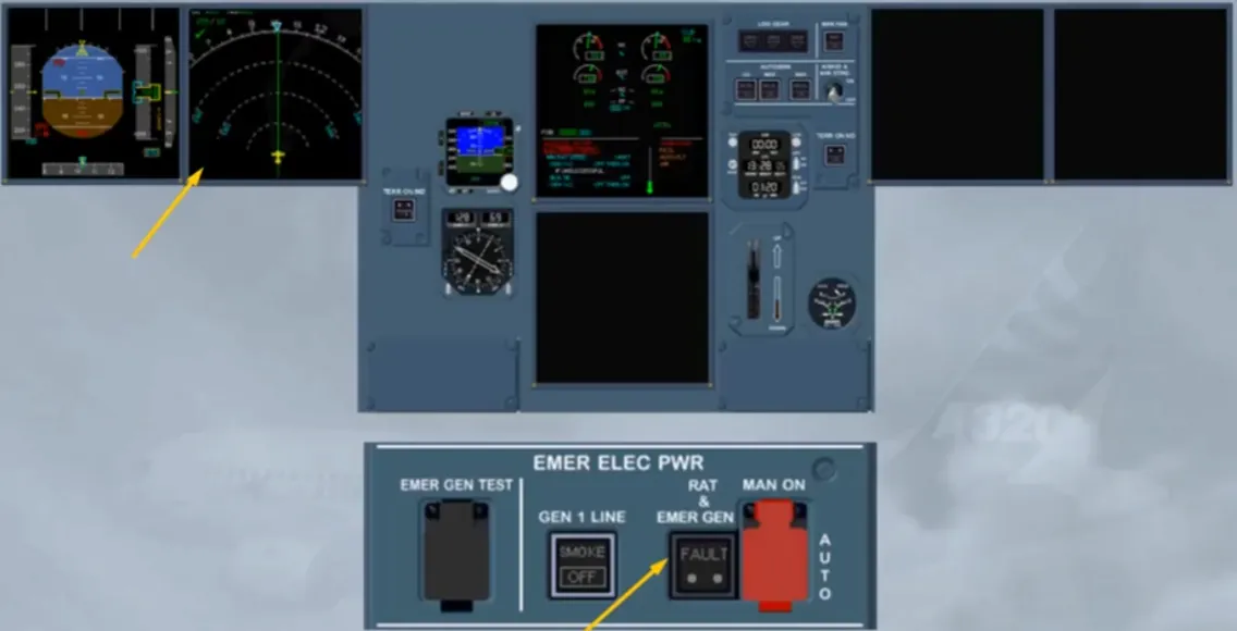
As you can see, the first consequence is that the power supply for the First Officer’s PFD and ND, the captain’s ND and the lower ECAM is lost. The SOP recommend, in such a case, that the CAPT will fly the aircraft while the First Officer does the ECAM action.
Note: another consequence is the loss of MCDUs 1 and 2.
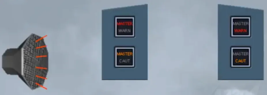
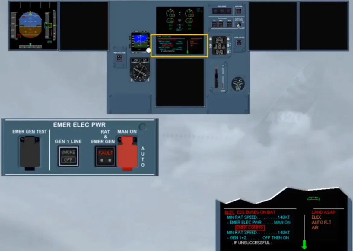
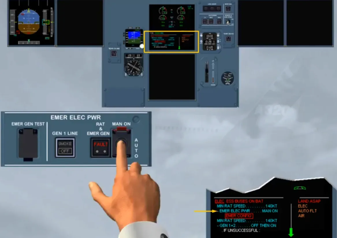
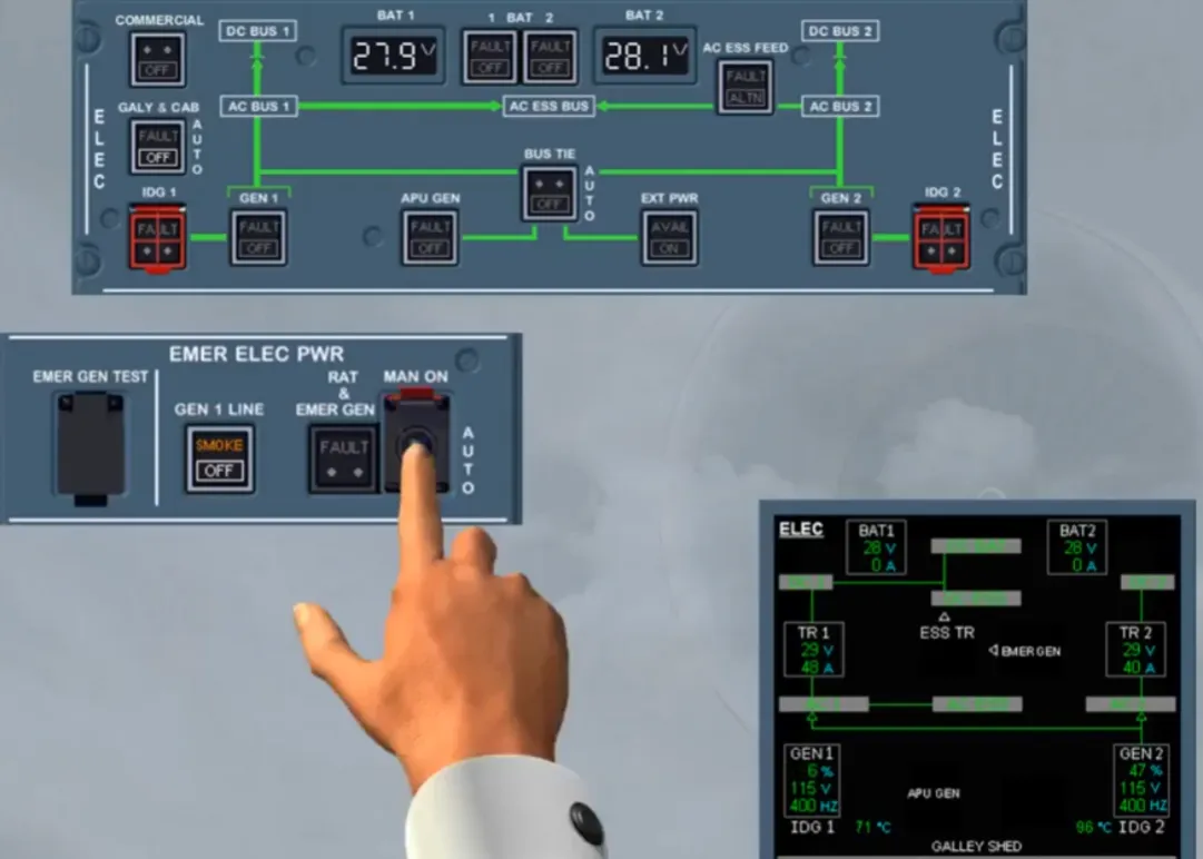
After clearing the MASTER lights and stopping the alarms, observe that on the EMER ELEC PWR panel, the red RAT & EMER GEN FAULT light is illuminated meaning that the emergency generator is not yet on line.
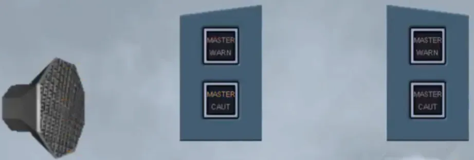
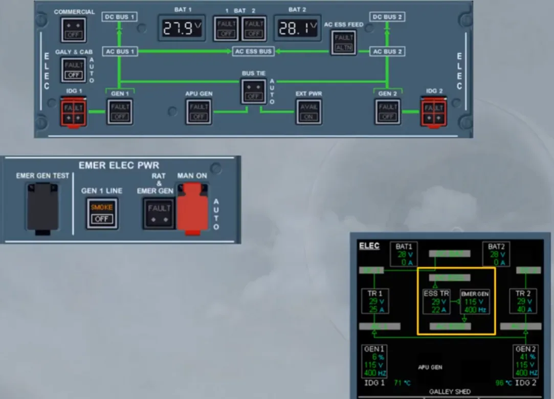
After a short lapse of time, the RAT & EMER GEN light disappears, the EMER GEN is now running and supplying the system.
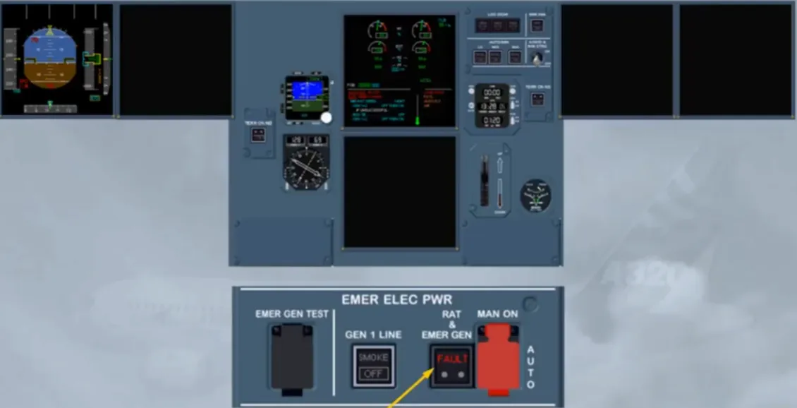
Notice that with the EMER GEN on line, the power supply to the Captain’s ND has been restored.
Note: MCDU 1 is also recovered.
On the EWD, you can read that the autopilot has disengaged. Let’s deal with this first.
To continue the procedure, we will clear this line by pressing on the CLR key.
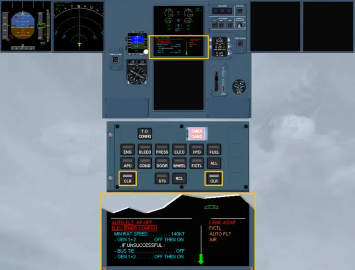
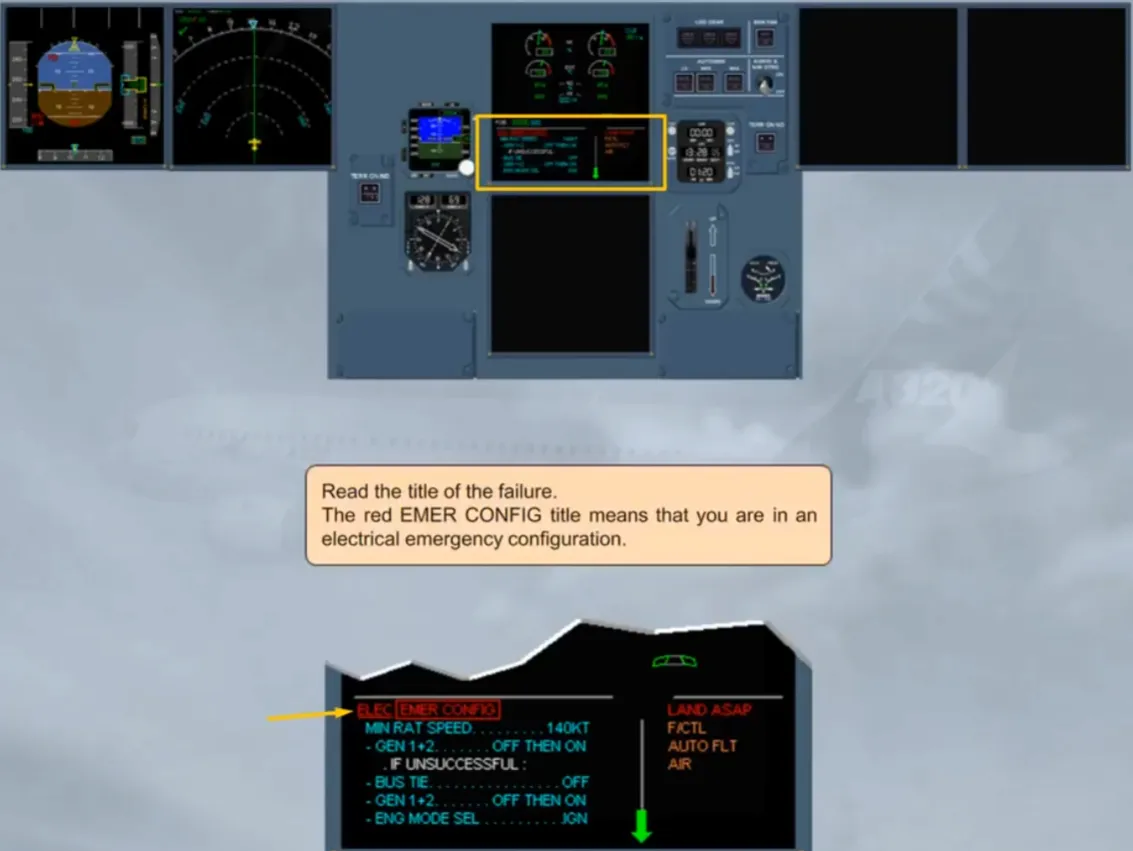
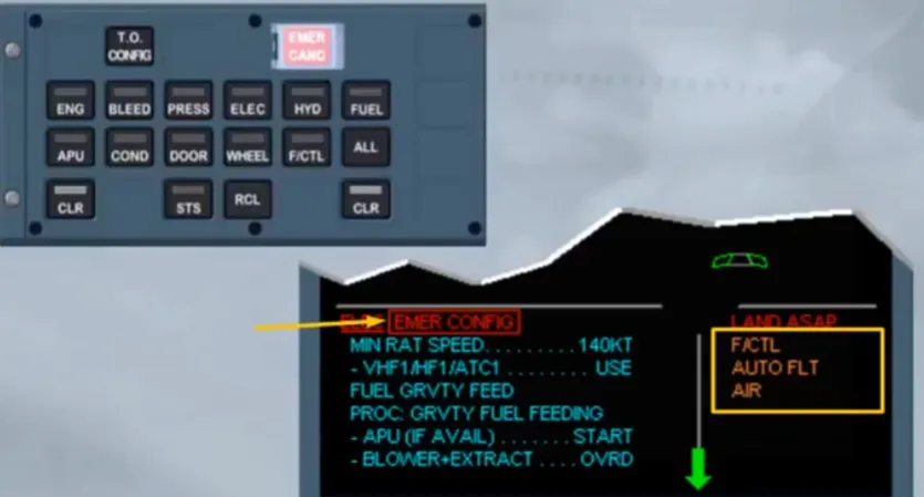
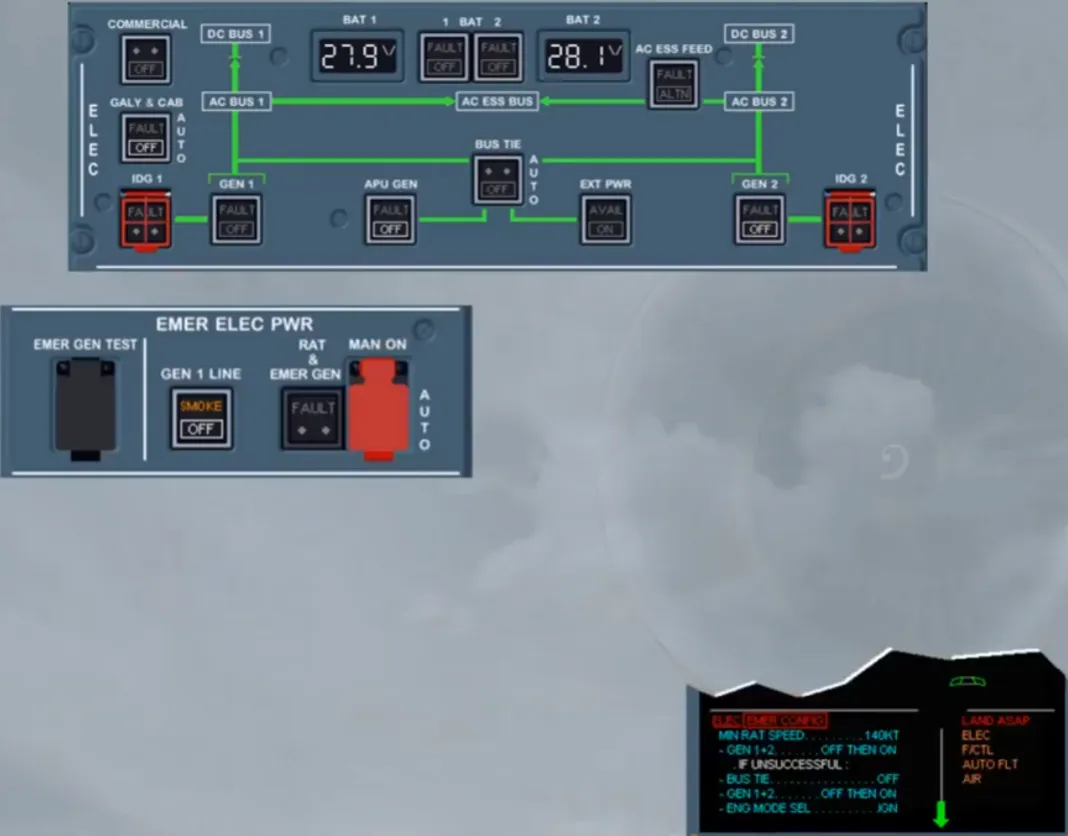
Read the title of the failure.
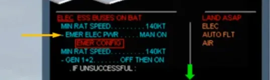
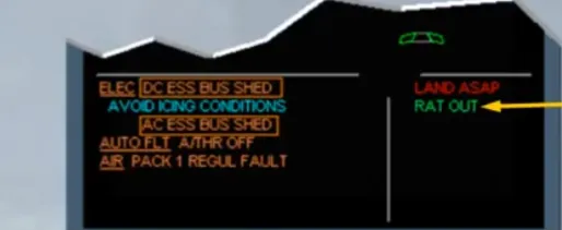
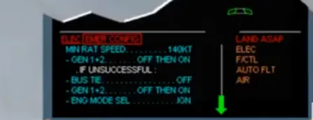
The red EMER CONFIG title means that you are in an electrical emergency configuration.
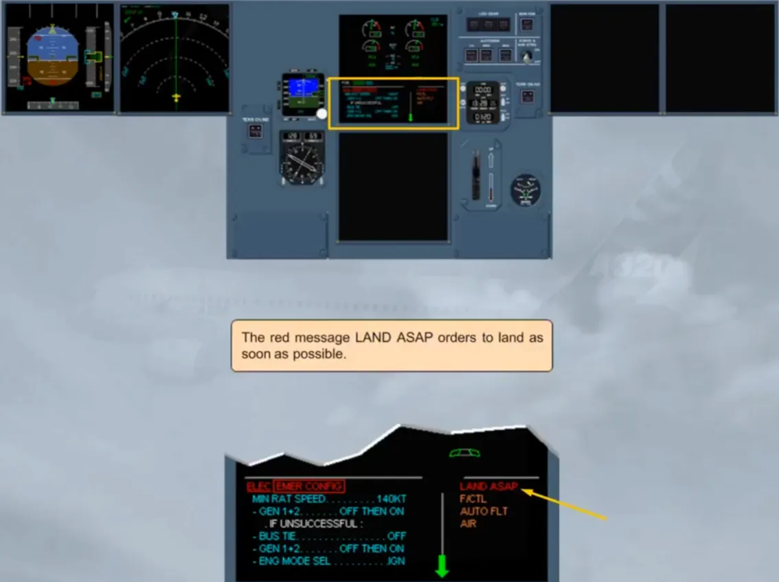
The red message LAND ASAP orders to land as soon as possible.
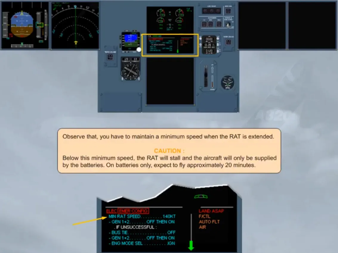
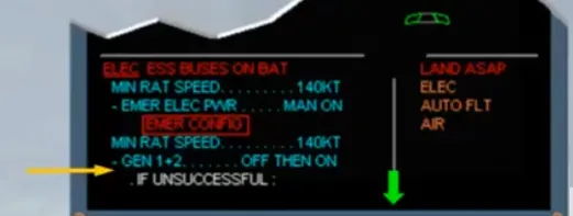
Observe that, you have to maintain a minimum speed when the RAT is extended.
CAUTION: Below this minimum speed, the RAT will stall and the aircraft will only be supplied by the batteries. On batteries only, expect to fly approximately 20 minutes.
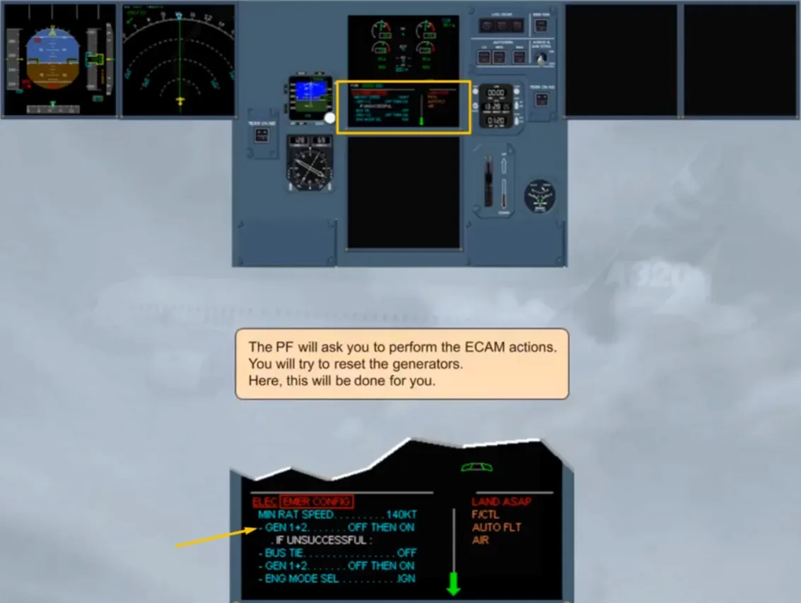
The PF will ask you to perform the ECAM actions. You will try to reset the generators. Here, this will be done for you.
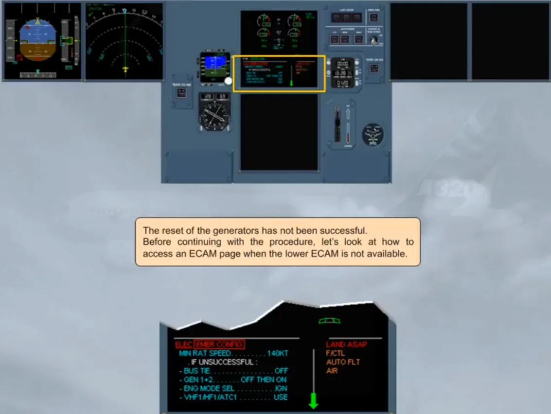
The reset of the generators has not been successful.
Before continuing with the procedure, let’s look at how to access an ECAM page when the lower ECAM is not available.
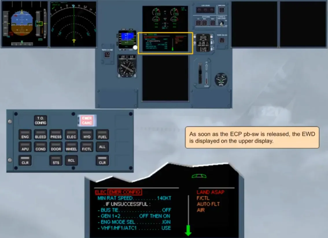
An ECAM page can be called up on the upper ECAM by pressing and holding its related system key on the ECP.
The page is displayed on the upper ECAM as long as the associated key is maintained pressed.
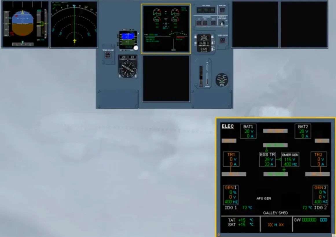
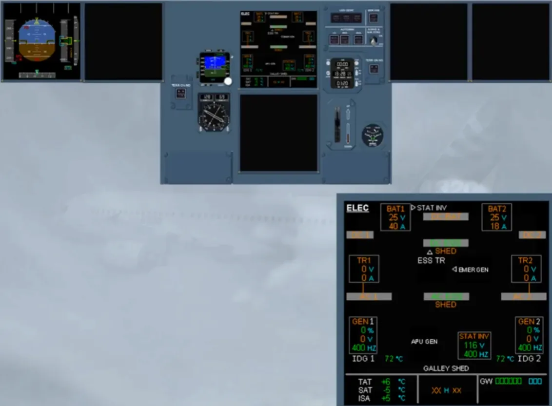
On the ECAM ELEC page, note that the EMER GEN supplies the AC ESS bus and, via the ESS TR, the DC ESS bus.
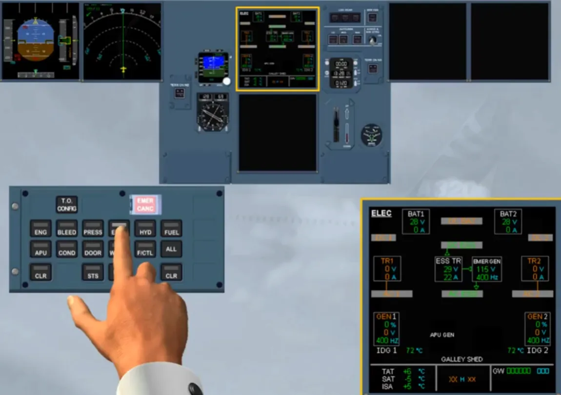
As soon as the ECP pb-sw is released, the EWD is displayed on the upper display.
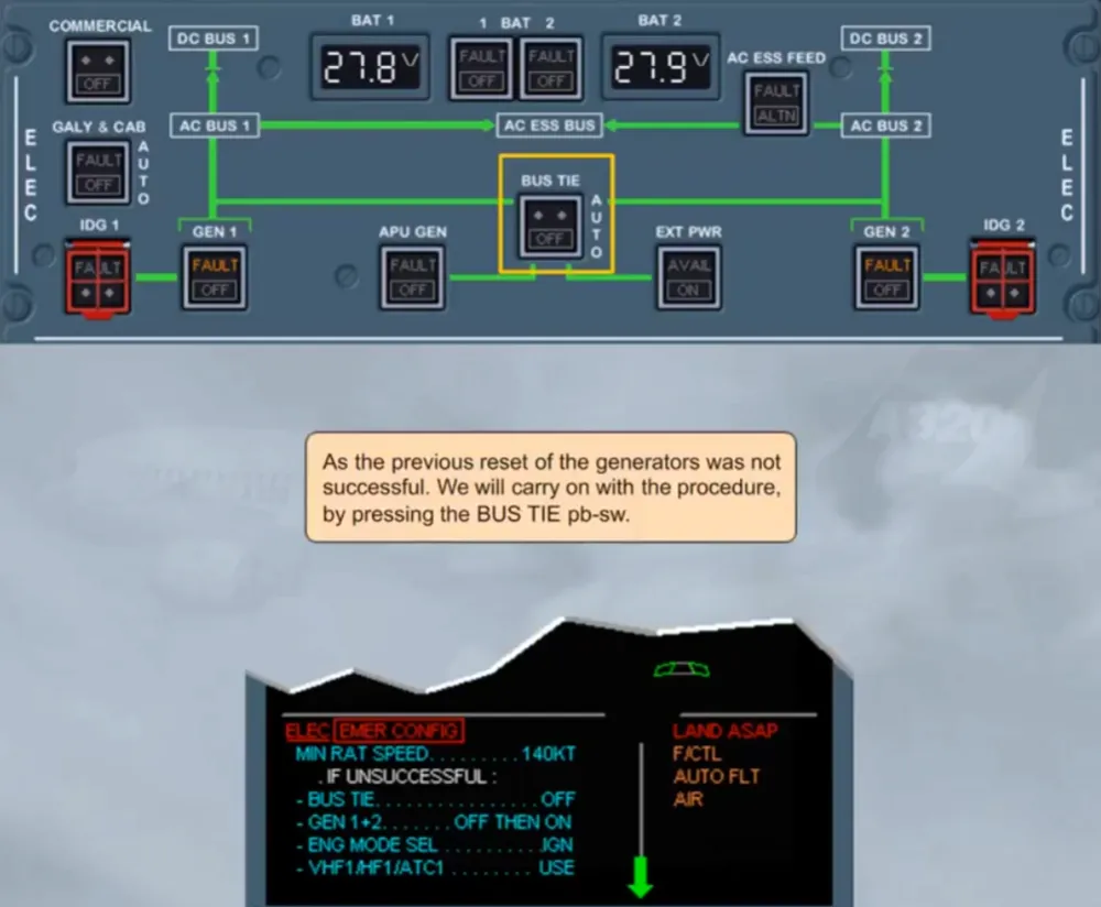
As the previous reset of the generators was not successful. We will carry on with the procedure, by pressing the BUS TIE pb-sw.
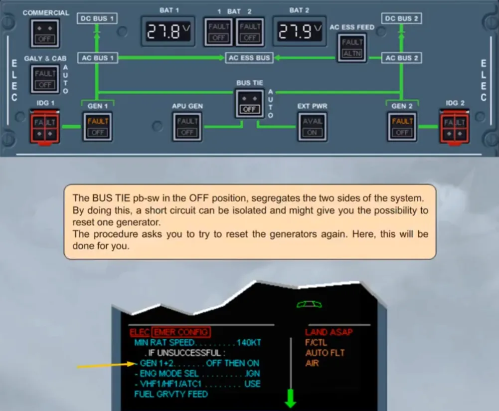
The BUS TIE pb-sw in the OFF position, segregates the two sides of the system. By doing this, a short circuit can be isolated and might give you the possibility to reset one generator.
The procedure asks you to try to reset the generators again. Here, this will be done for you.
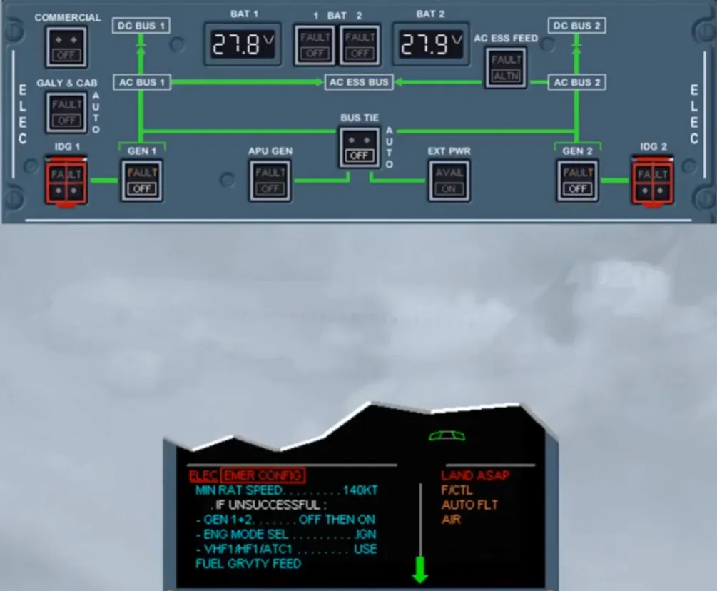
Again, the reset of the generators has not been successful.
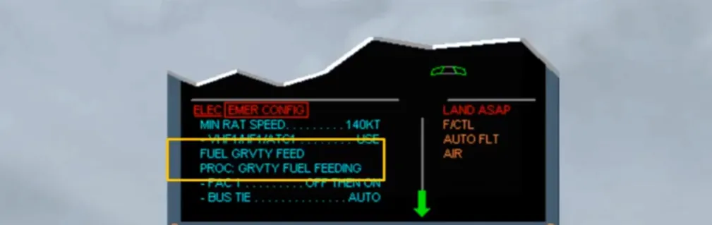
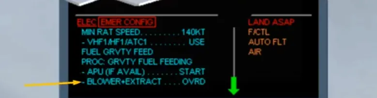
The next action will concern the ignition as the fuel pumps are not available and so the engines are fed by gravity. We did this selection for you.
Avoid negative G and apply the gravity fuel feed procedure (QRH).

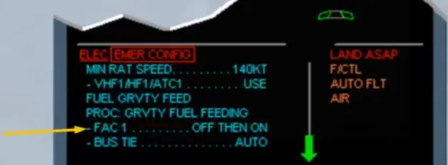
Then, the Flight Augmentation Computer (FAC) 1 must be reset. We did it for you. This allows the recovery of:
- The rudder trim system but without trim position indication and
- On the PFD 1, the characteristic speeds, the speed protections and the speed trend arrow.
Then the BUS TIE pb-sw must be set back to AUTO. This may allow the APU generator to take over on at least one side after starting the APU.
Note: The APU must be started only below FL 250.
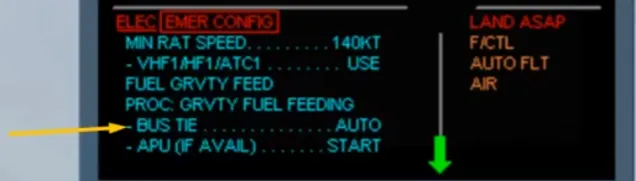
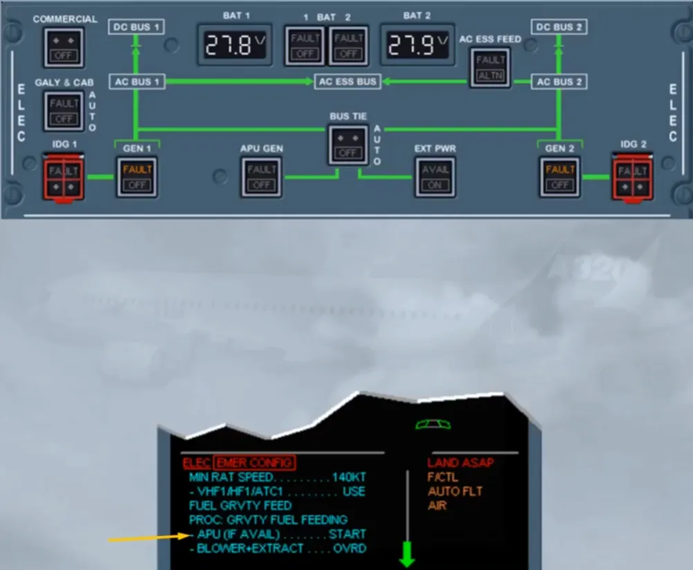
So, the BUS TIE pb-sw has been set back to AUTO. Then below FL 250, you may start the APU, only if it is available.
Note: When the APU MASTER SW pb is set to ON, the batteries are connected to the DC BAT bus for a maximum of 3 minutes.
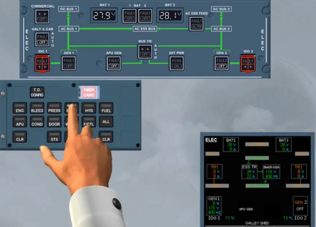
As the next step concerns another system, we will stop here and study the indications on the right side of the EWD.
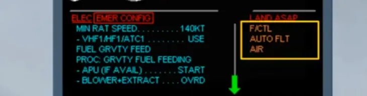
Notice the amber F/CTL, AUTO FLT and AIR system titles. This means that these systems are affected by the boxed primary failure. Their related procedures are stacked after the current one and will appear with the completion of the primary failure procedure. For that we have cleared the boxed primary failure for you.
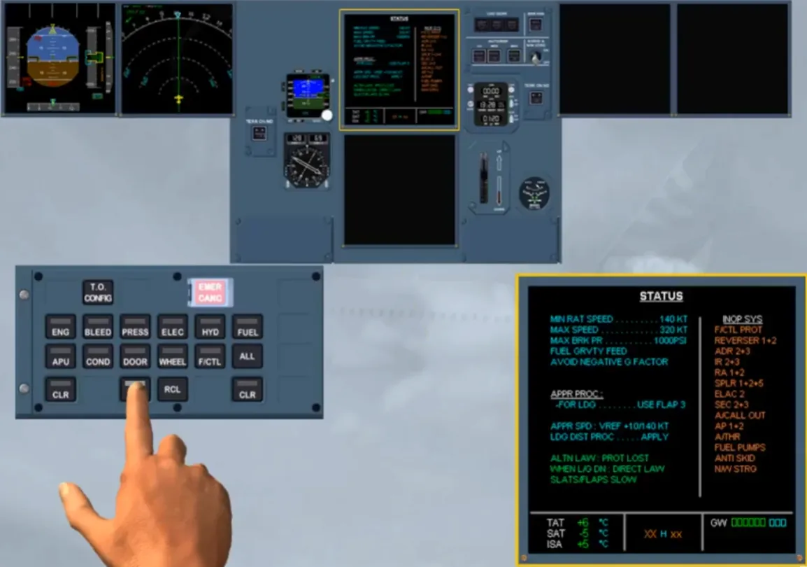
After clearing the affected system titles, the memo is displayed with a white STS. Again the related key on the ECP must be pressed and held to display the STATUS page on the ECAM upper display.
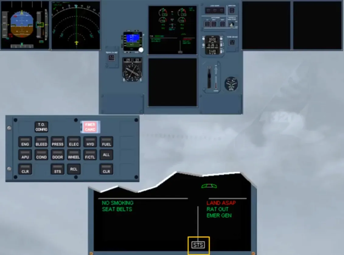
As long as the STS key is kept pressed, the STATUS page is displayed and can be reviewed.
The listed inoperative systems are those seen by the ECAM. For more, refer to your documentation.
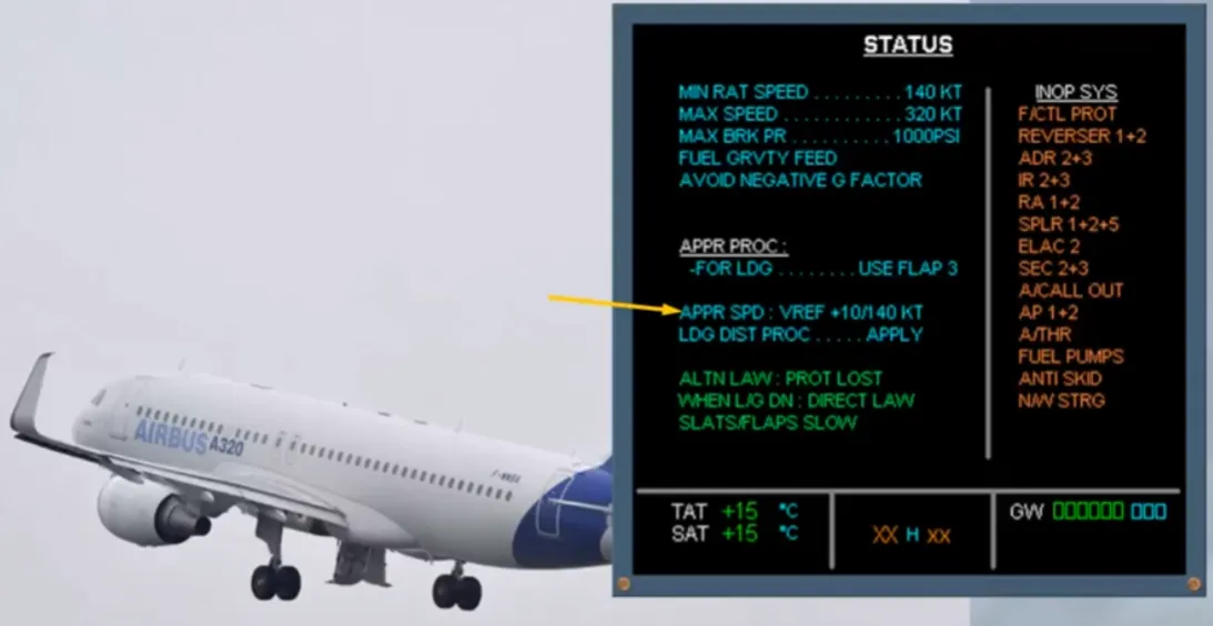
Even if the RAT is able to hydraulically drive the emergency generator correctly down to 125 kt, the approach speed should not be below 140 kt.
Let’s see what happens when the RAT stalls or when the aircraft is already on ground with the speed below 100 kt.
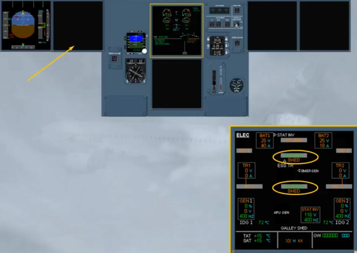
As soon as the RAT is not able to hydraulically drive the emergency generator, the electrical network is automatically transferred to the batteries and to the static inverter. As a consequence, the DC and AC essential buses are still supplied but they are partially shed, leading to the loss of the ND 1 and the MCDU 1. Note: This can be checked on the ECAM ELEC page if it has been selected (of course, for training only).
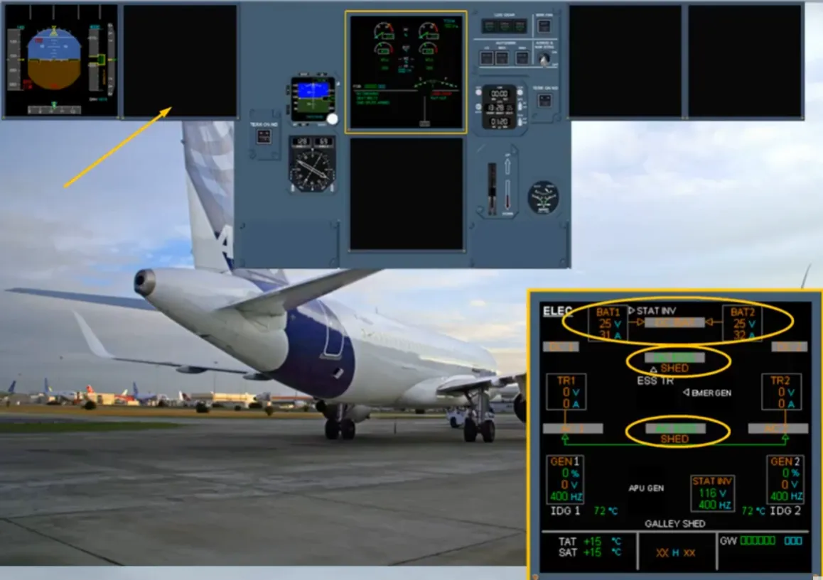
But when the aircraft is on ground and below 100 kt, the DC BAT bus is now supplied, allowing also the start of the APU (if available).
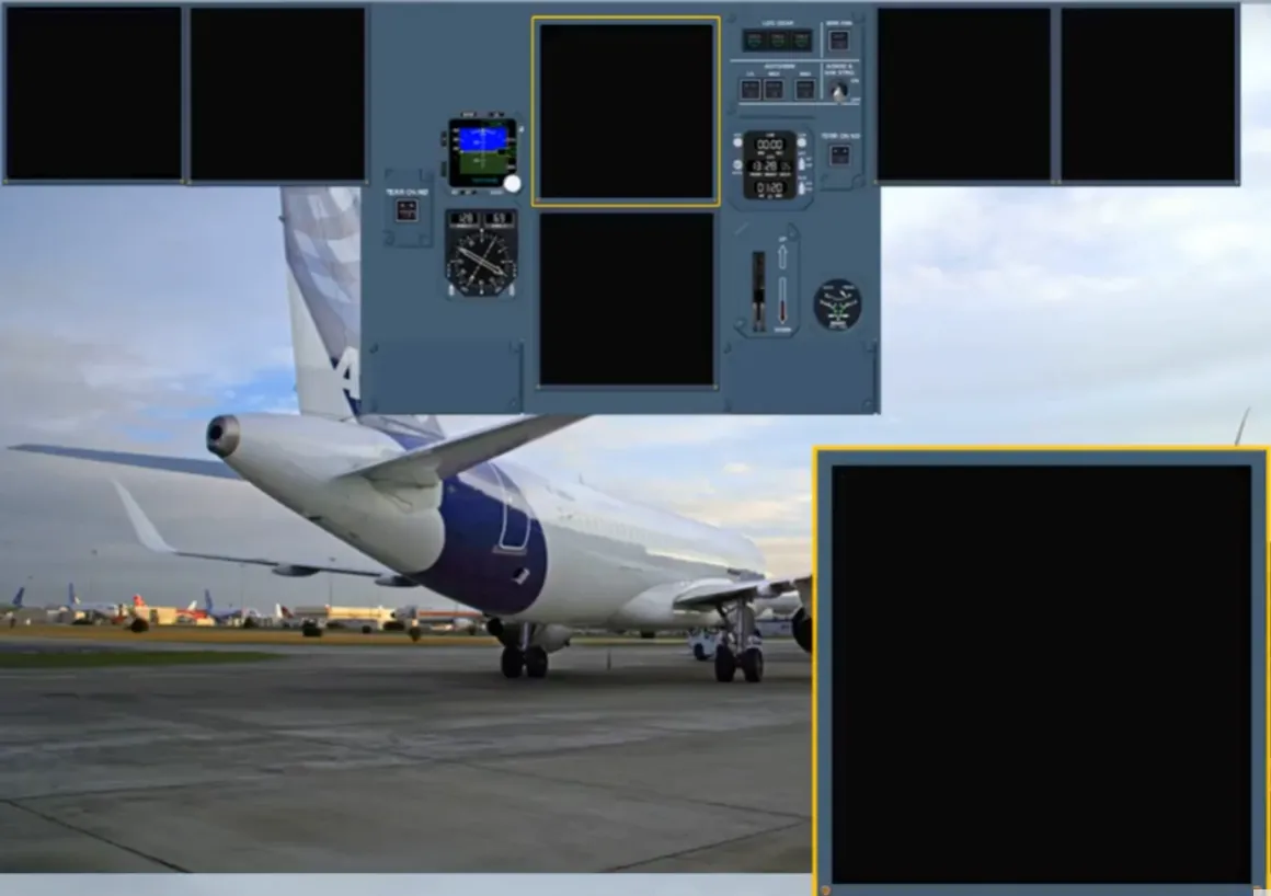
On ground, if APU generator cannot be connected to the electrical network, as soon as the speed is below 50 kt, all remaining display units are lost.
We will now review some indications we did not have the opportunity to see when performing the previous procedures.
As a result of the loss of AC bus 1 and AC bus 2 and provided the speed is above 100 kt, the RAT is automatically extended.
During the RAT extension before the emergency generator comes online, the electrical system is powered from the batteries and the static inverter, as shown (for training only) on the selected ECAM ELEC page.
Note: The approximate flight time on batteries is 20 minutes.
If the RAT fails to extend or if the emergency generator fails to be online, the red FAULT light, on the EMER ELEC PWR panel, will remain on and on the E/WD the related procedure is displayed.
Notice a new action is displayed, as the emergency generator is not on line. So, we did it for you.
But as you can see, it is not successful.
Also the engine generator resets are not successful.
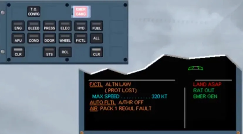
As the rest of the EMER CONFIG procedure has been already studied, we cleared it in order to display the next procedure.
Note: If the RAT has failed to extend the green memo RAT OUT will be not displayed.
Also the APU (if available) can be started but only when the aircraft is on ground and below 100 kt.
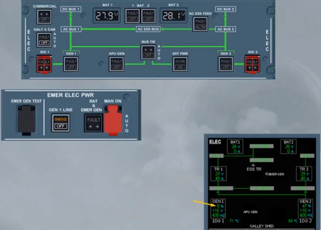
Now, let’s assume we are in flight.
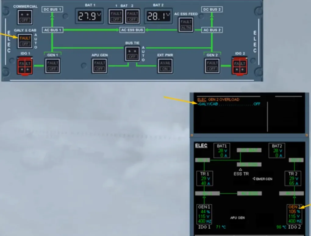
A generator overload has just occured.
Observe:
- On the ECAM ELEC page, the related GEN and load indications are in amber indicating that the load is above 100% of rated output
- On the ELEC panel, an amber FAULT light comes on, helping you to locate the pb-sw corresponding to the procedure and in order to reduce the load on the faulty generator.
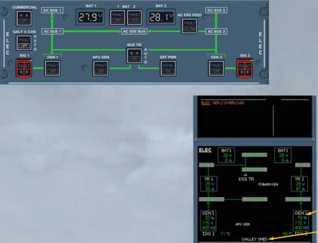
So, we did the action for you.
Observe:
- On the ECAM ELEC page, the white GALLEY SHED appears and the load indication has returned to normal.
Note: All galley circuits, and if installed the in-seat power and the IFE systems, are not supplied.
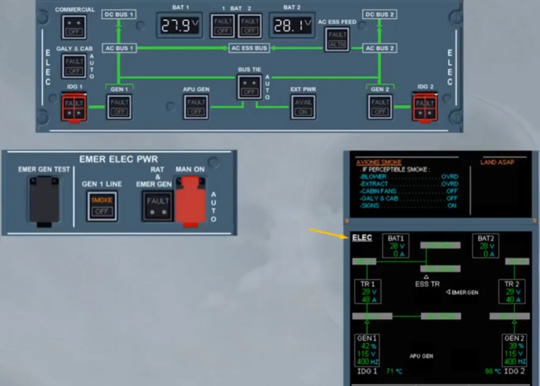
Now, let’s assume we are again in flight. A smoke has been detected in the air extraction duct of the avionics ventilation system.
Observe:
- The ECAM ELEC page has been automatically displayed
- On the E/WD, after the ECAM actions are done, you have to refer to QRH in order to set manually the EMER ELEC CONFIG
- On the EMER ELEC PWR panel, an amber SMOKE light comes on, helping you to locate the pb-sw corresponding to the QRH procedure.
Note: Here we will see items belonging to the electrical system.
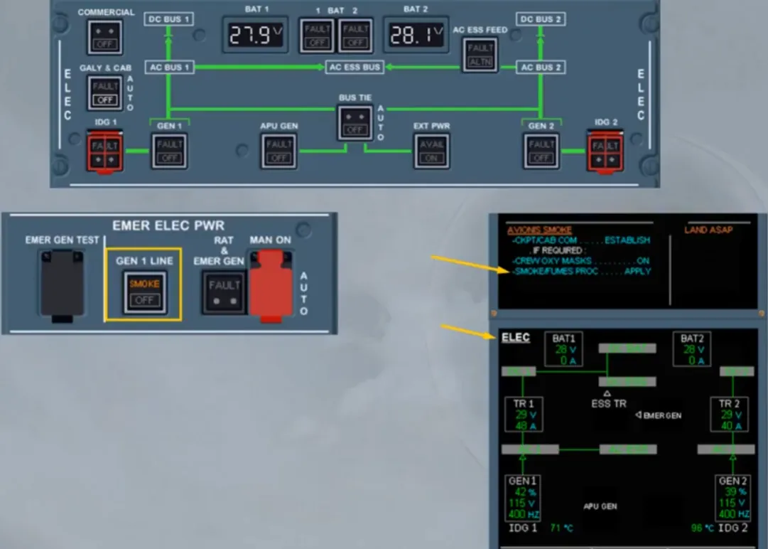
When the GEN 1 line pb-sw is set to OFF, the generator 1 line contactor is open. This connects the AC bus 1 to the generator 2 and the fuel pumps, normally supplied by the AC bus 1, are transferred to the output of the generator 1, in order to avoid the fuel gravity feeding configuration when the EMER ELEC CONFIG is set. To set the EMER ELEC CONFIG, the RAT & EMER GEN pb must be pressed to start the emergency generator. Then when it is on line, as shown on the ECAM ELEC page, the APU GEN and GEN 2 pb-sws must be set to OFF.
As soon as the GEN 2 pb-sw is set to OFF, the emergency electrical configuration is set, as shown on the E/WD and also on the ECAM ELEC page when it is maintained displayed on the E/WD. So, we will stop here, as you should continue to apply the QRH, to know which part of the ECAM has to be followed..
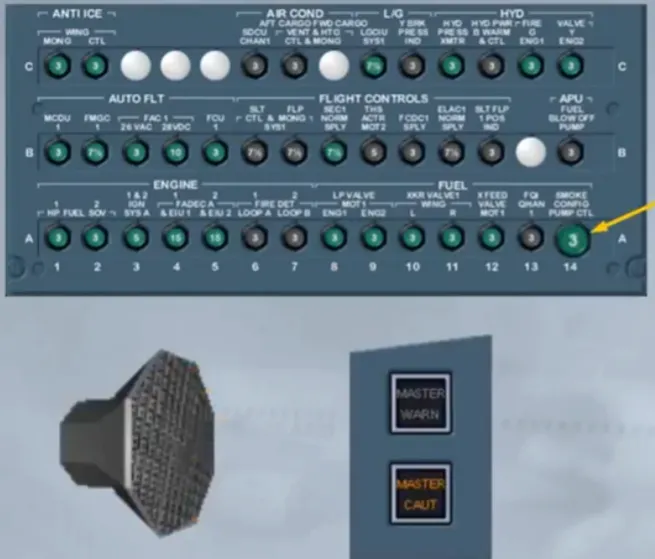
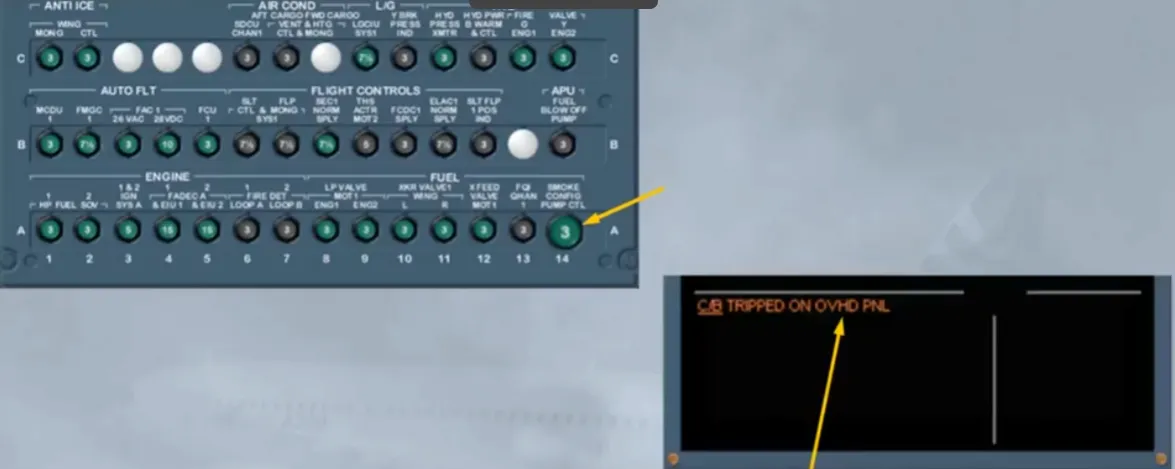
When a green Circuit Breaker (C/B) has tripped for more than 60 seconds, an ECAM caution is triggered and indicates which panel is affected.
Note: The black C/Bs are not monitored by the ECAM.
Module completed
Video study
Section titled “Video study”- Watch the video available on YouTube