Air Conditioning System
Like the majority of the systems on the A320 the Air Conditioning system is fully automatic, and is designed to provide a comfortable atmosphere in which to work and travel.
We will begin our study of the system by first looking at the air conditioning packs.
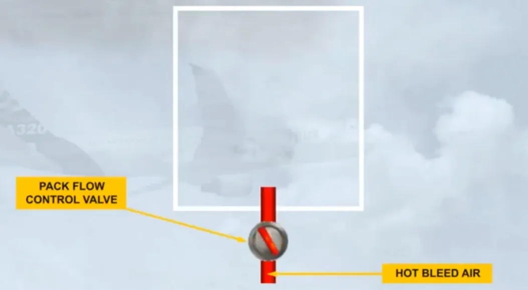
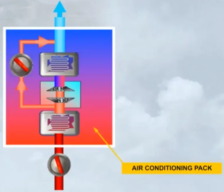
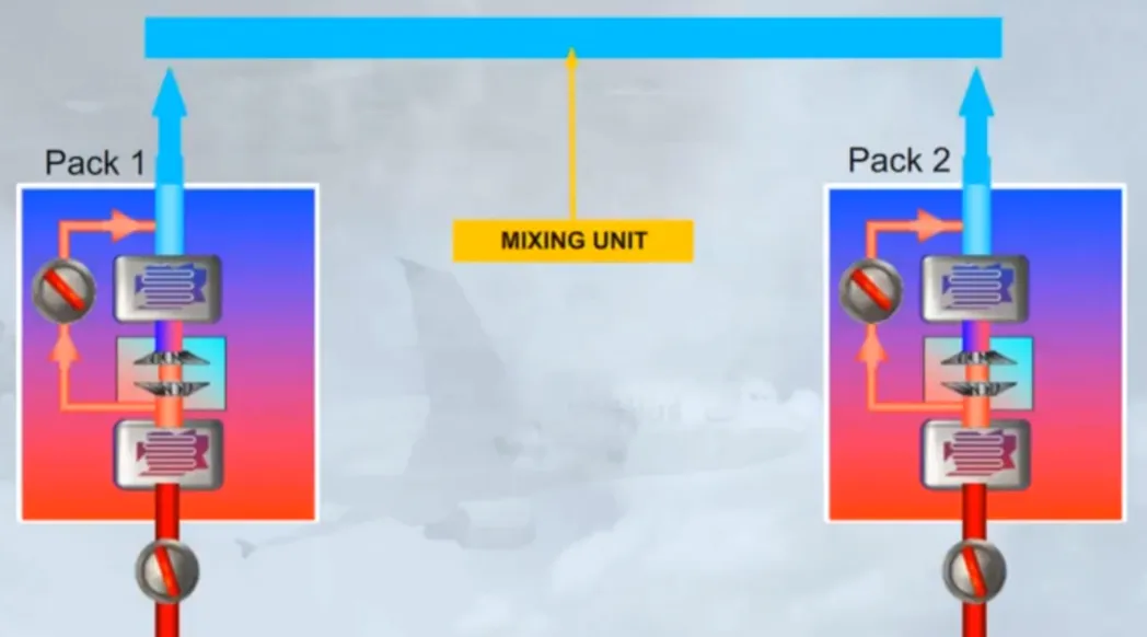
The A320 is equipped with two Air Conditioning Packs, located in the wing root area, forward of the Landing Gear Bay. Let’s look at how a pack works.

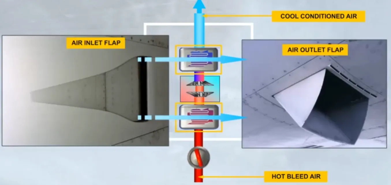
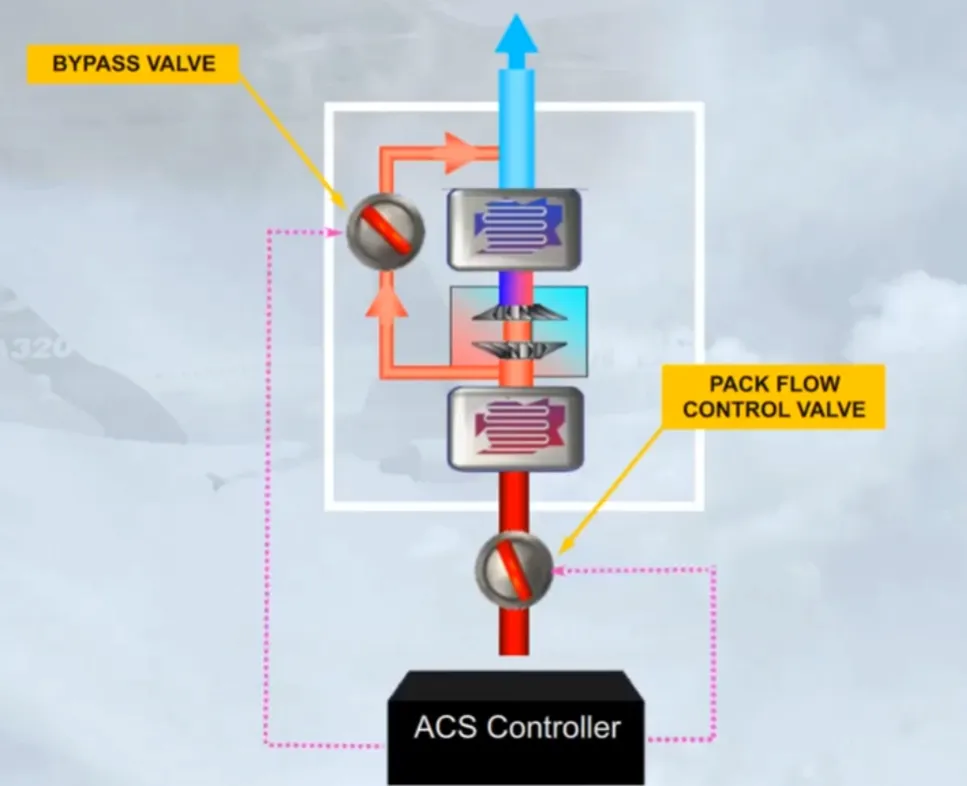
Hot bleed air enters the pack via a Pack Flow Control Valve. Its function is to adjust the flow rate through the pack.
The air then passes through several stages within the pack (heat exchangers and air cycle machine), so that it is cooled to provide a conditioned air output.
In fact sub zero temperatures can be achieved.
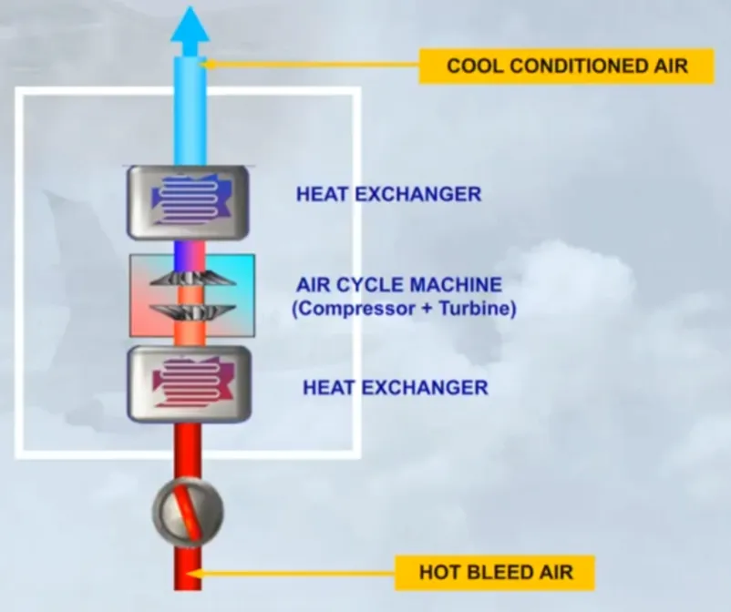
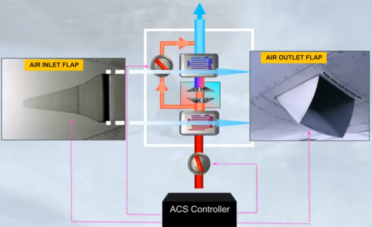
Two of the stages are heat exchangers. They cool the hot bleed air using the flowing ambient air. This flow of air enters via the Ram Air Inlet Flap and exits via the Ram Air Outlet Flap.
So that the output temperature of the pack can be adjusted a bypass valve is fitted.
This valve allows warmer air to be mixed with the cold air.
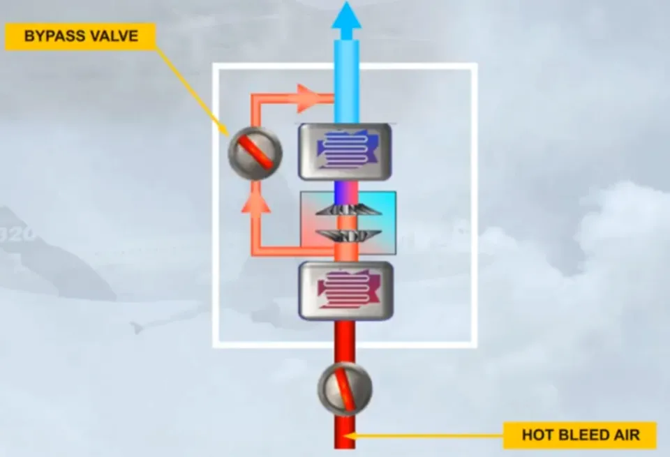
The Pack Flow Control Valve, and the bypass valve, are regulated by a related Air Conditioning System Controller to vary the flow rate and the output temperature.
The related ACS Controller also controls the related ram air inlet and outlet flaps to adjust the amount of air blowing through the heat exchangers.
Note: the related ram air inlet flap closes during take-off and landing to avoid ingestion of foreign matter.
To make things simpler, let’s define the area within the white box as a pack.
The two Air Conditioning Packs operate automatically and independently to provide cool conditioned air.
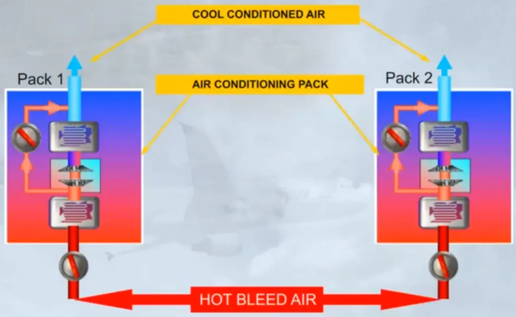
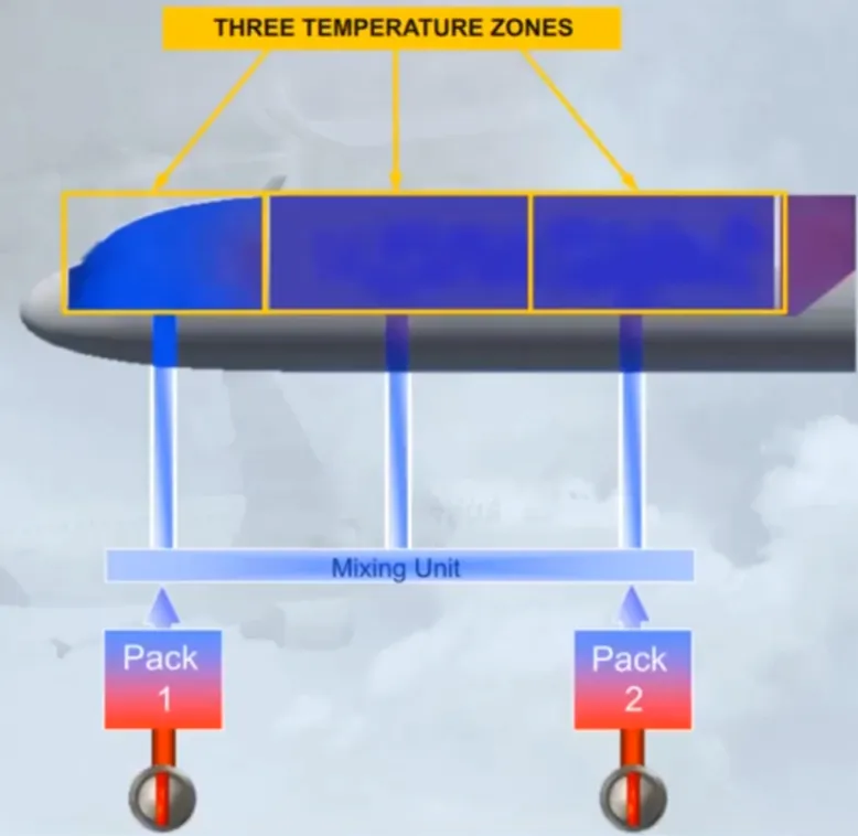
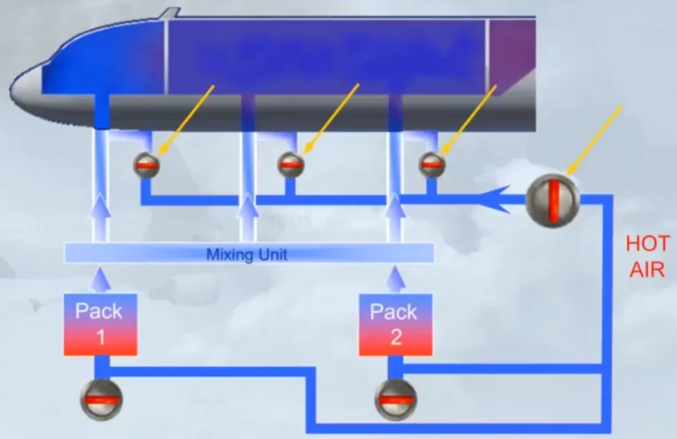
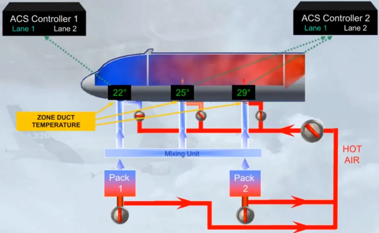
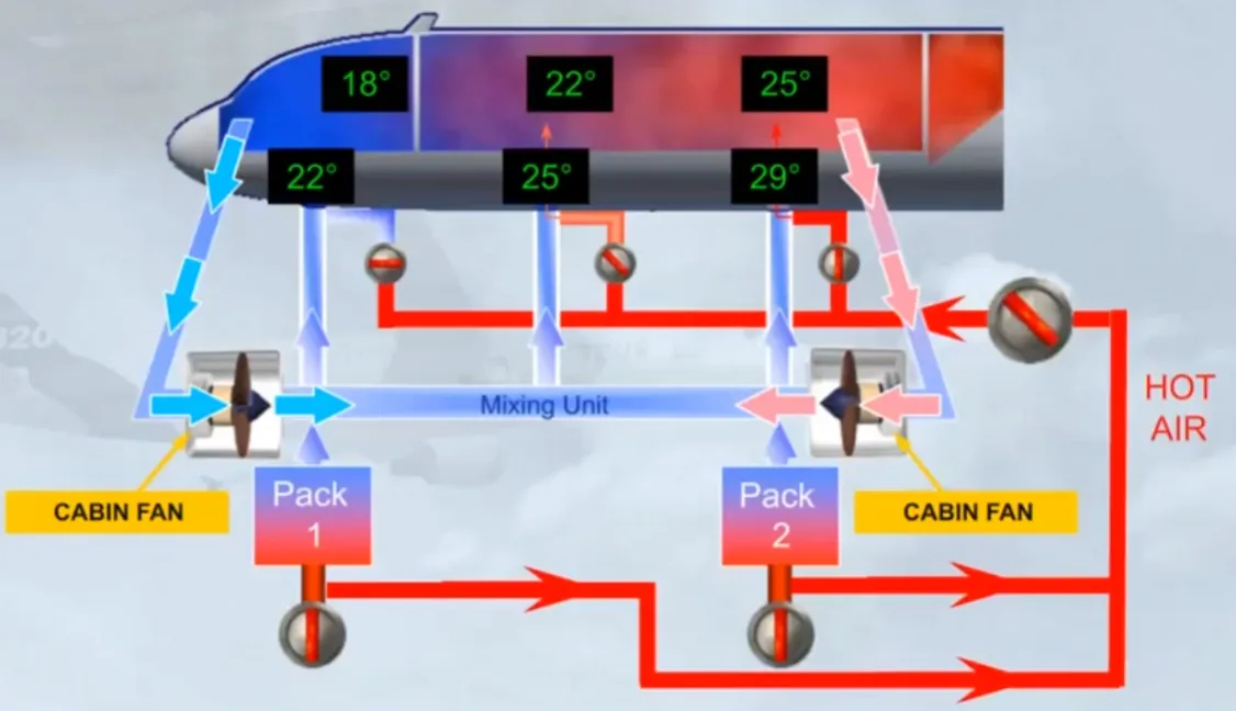
The conditioned air from the packs is then fed to a Mixing Unit.
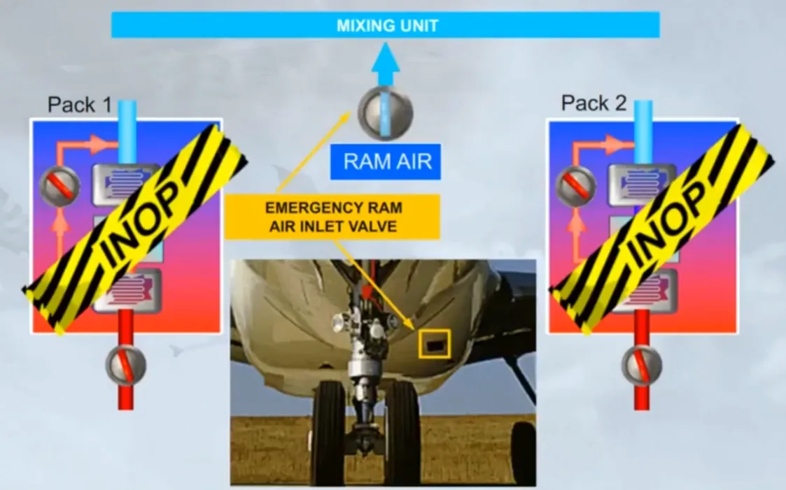
In case of failure of both packs, ram air is provided via an emergency RAM AIR valve. We will look at the use of RAM AIR, in the failure cases module.
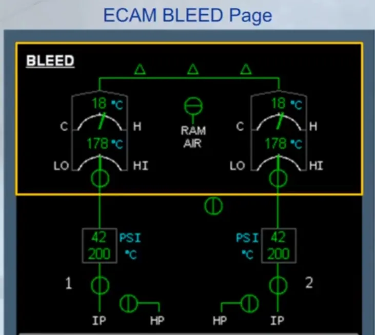
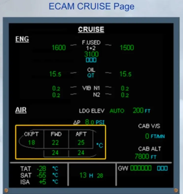
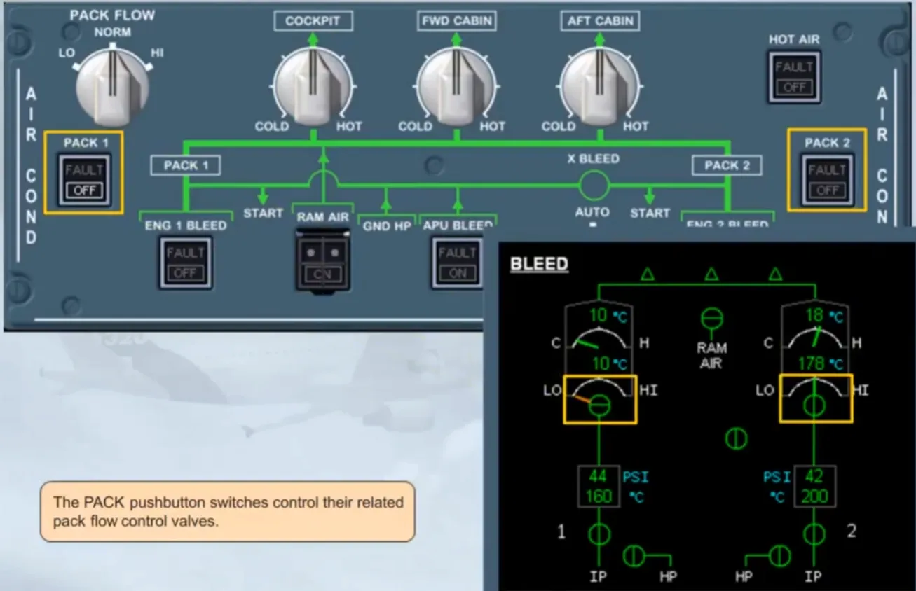
Various pack parameters are monitored on the ECAM. They are:
- Pack flow
- Compressor outlet temperature
- Bypass valve position
- Pack outlet temperature
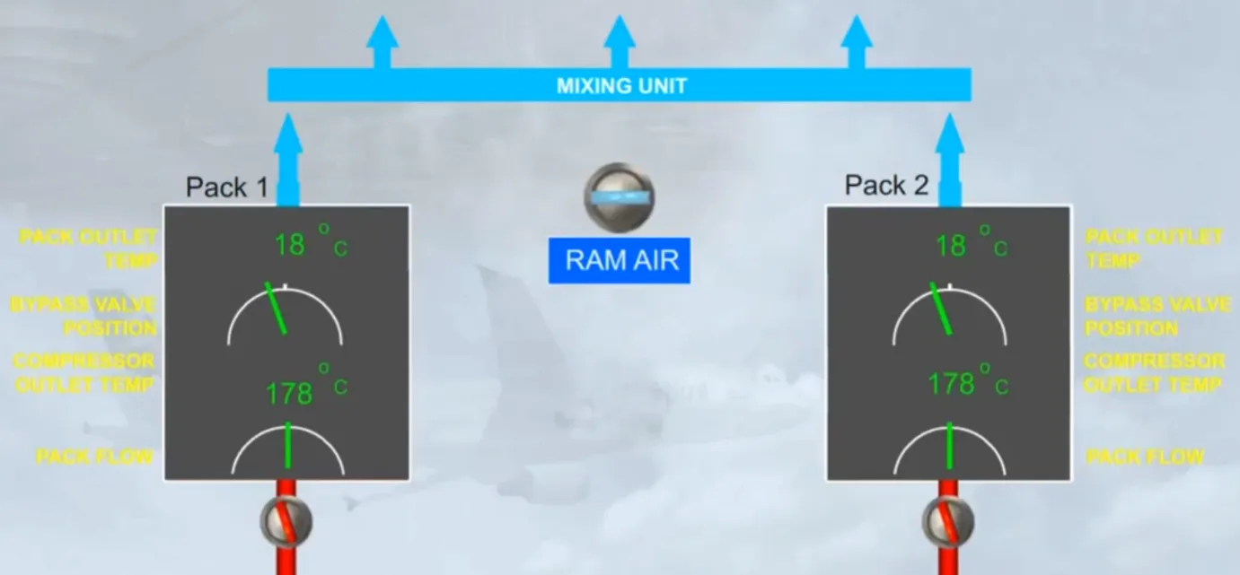
These parameters, along with the valve positions, are displayed on the upper part of the ECAM BLEED page.
Having discussed the air conditioning packs, we will now look at how temperature and flow regulation is achieved throughout the aircraft.
The three outputs from the mixing unit feed three separate aircraft zones:
- Cockpit
- Forward cabin
- Aft cabin.
Let’s look at how the temperature of the zones is controlled.
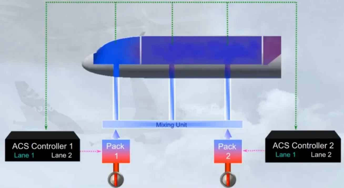
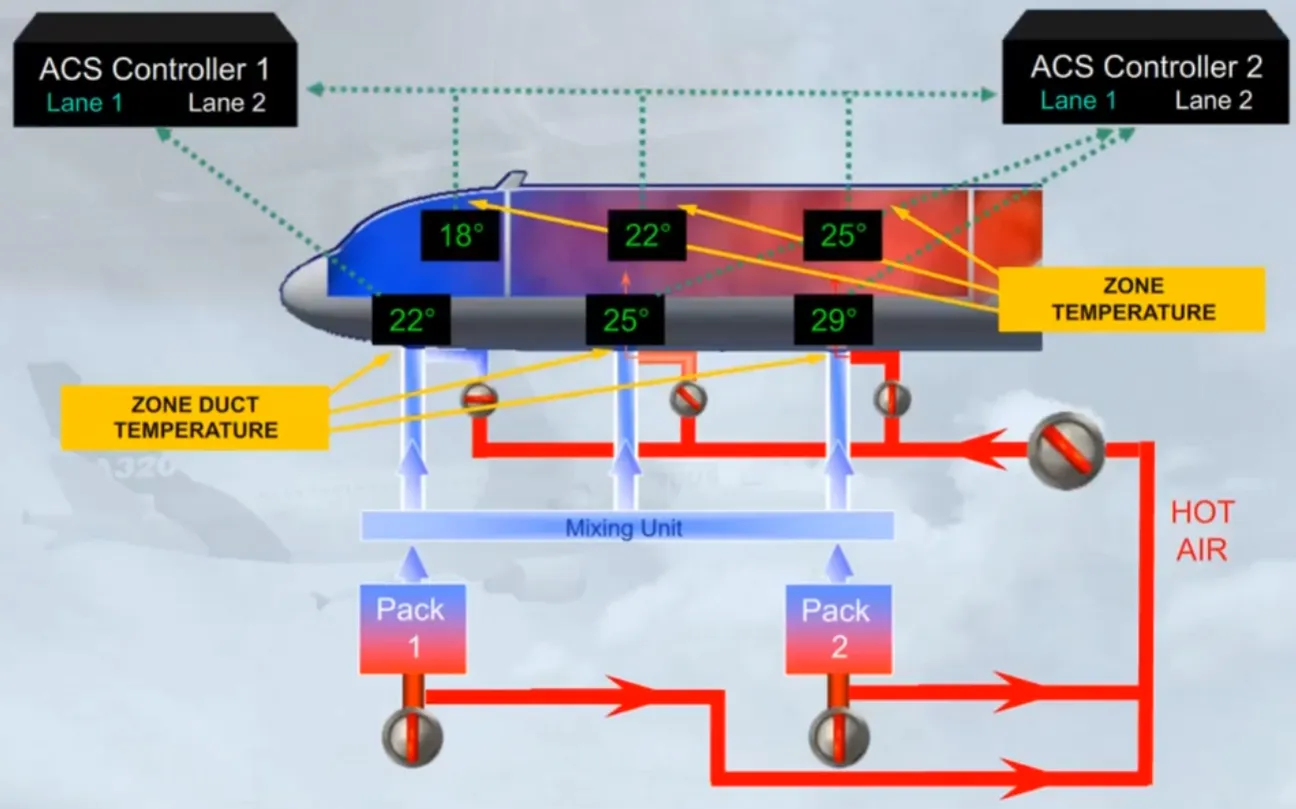
The two ACS Controllers monitor the temperatures of the three zones and send signals to set the air temperature delivered by the related pack.
Each ACS Controller comprises two lanes, one active and the other in standby:
- In case of one lane failure, the second lane takes over
- In case of both lanes failure, the related pack is lost.
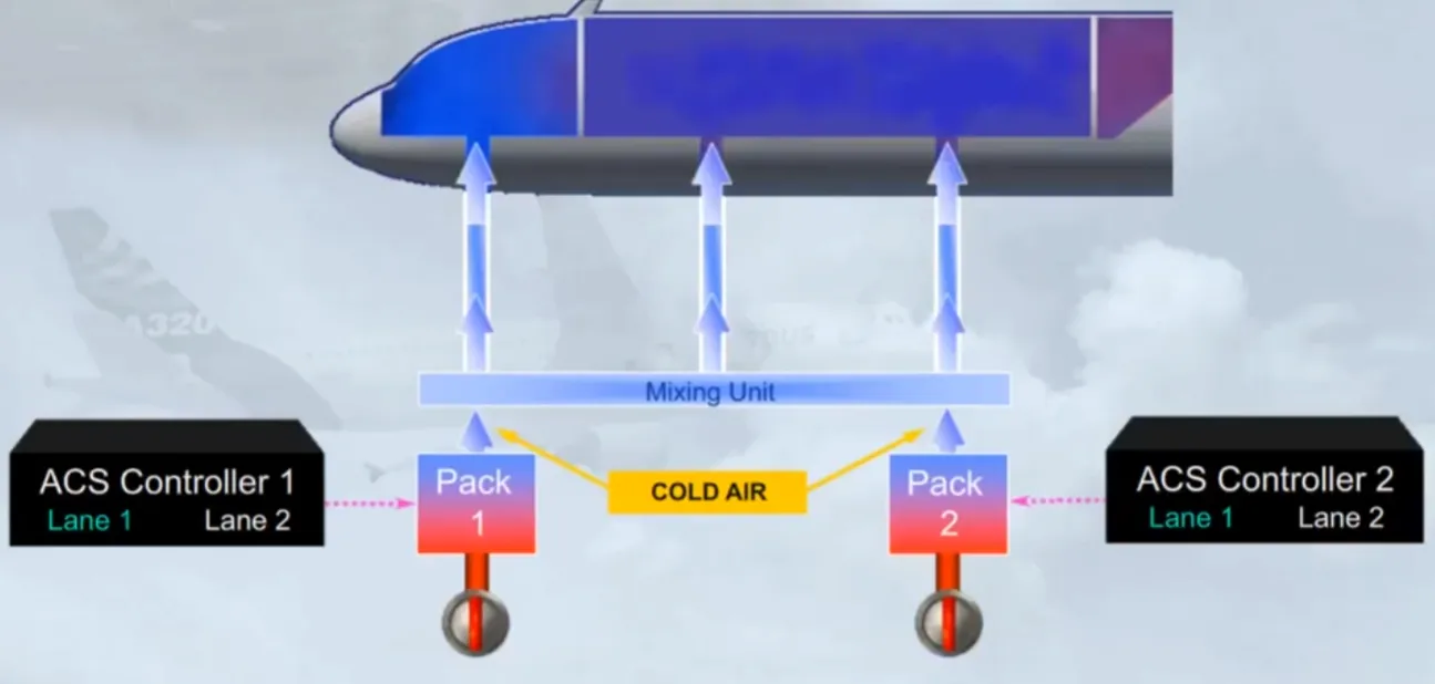
Normally cold air is delivered by the packs and is then sent to the three zones.
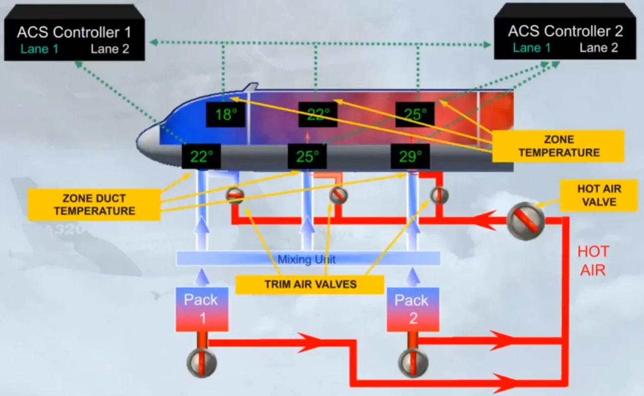
Since the different areas of the aircraft may require different amounts of cooling, or heating, hot bleed air can be added via Trim Air Valves to obtain the demanded temperature for a zone.
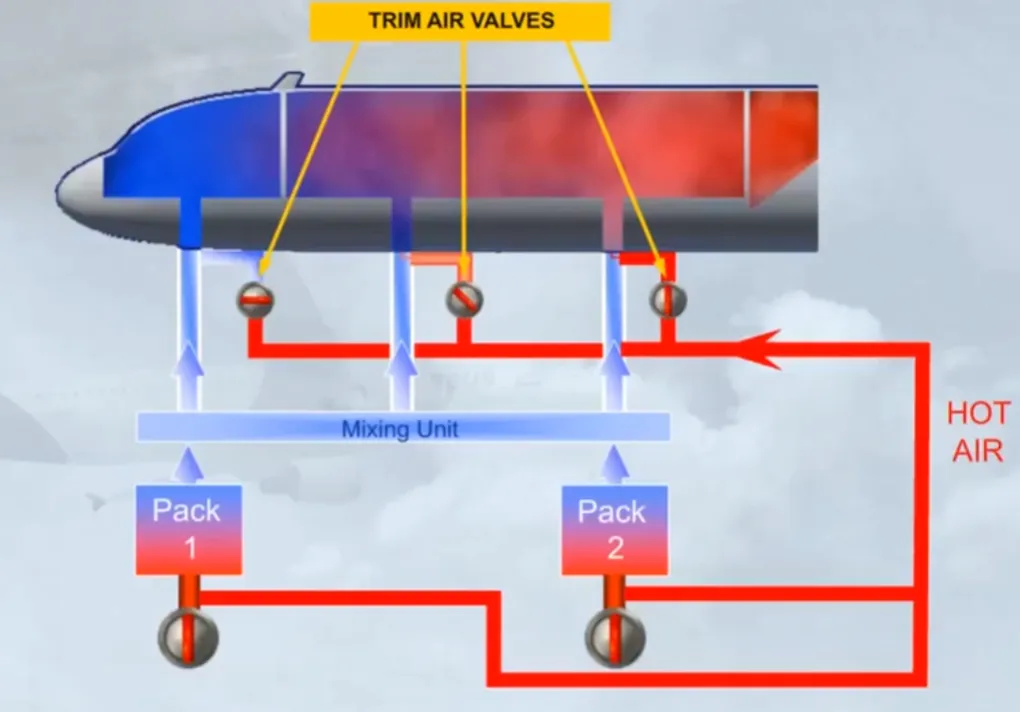
In the example shown:
- No hot air is being added to the cockpit zone
- Some hot air is being added to the forward cabin zone
- A lot of hot air is being added to the aft cabin zone.
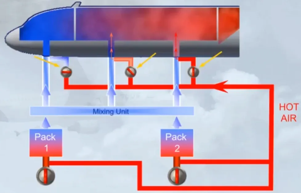
The Trim Air Valves are supplied via a Hot Air Valve. It regulates the pressure of the hot air supplied to the trim system and works as a shut off valve.
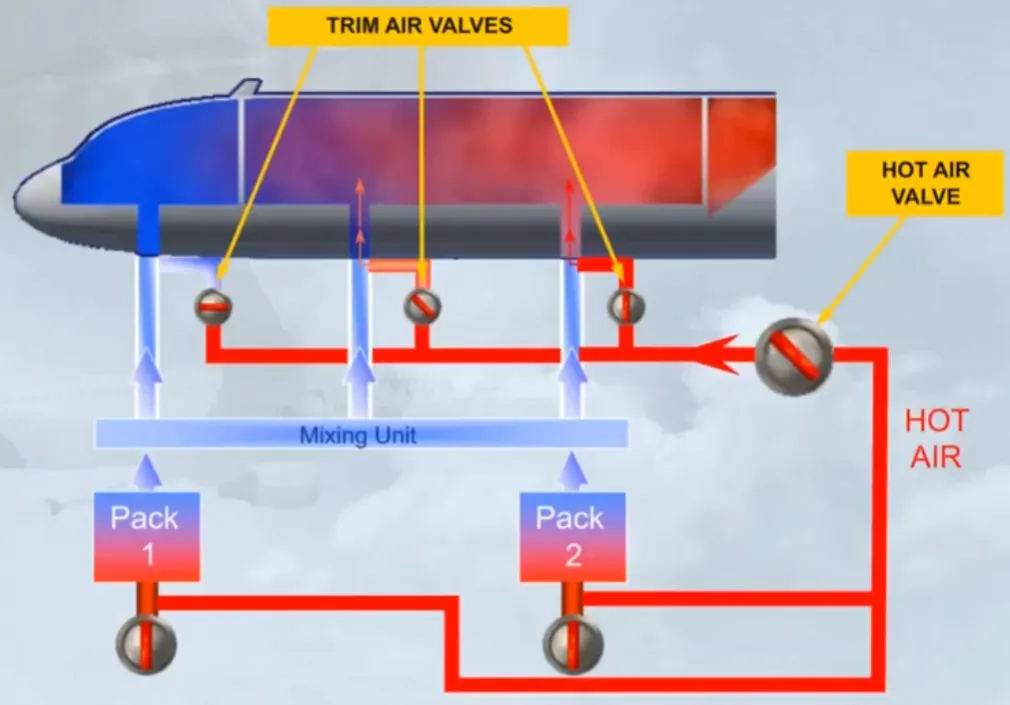
The hot bleed air is supplied to the hot air valve downstream of the pack flow valves. This means that if the pack flow valves are closed there is no air supplied to the trim system. The hot air valve and the trim air valves will automatically close.
The ACS Controller 1 controls the cockpit TRIM AIR valve and the HOT AIR valve.
The ACS Controller 2 controls the FWD and AFT cabin TRIM AIR valves.
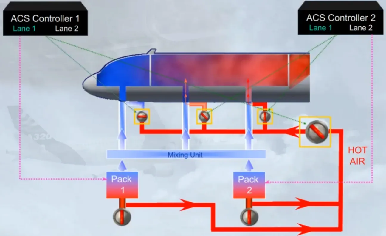
The related zone duct temperature, which is the temperature of the air entering a zone, is also monitored by the ACS CONTROLLER:
- Cockpit duct temperature by the ACS Controller 1
- FWD and AFT duct temperatures by the ACS Controller 2.
The related zone temperature, which is the temperature of the ambient air, is also monitored by both ACS Controllers.
The zone duct temperatures and the zone temperatures, the trim air valves and the hot air valve are shown on the ECAM AIR COND page.
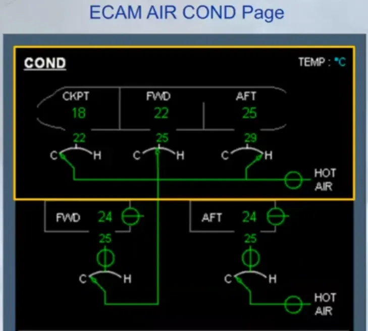
The ECAM CRUISE page also contains zone temperature indications.
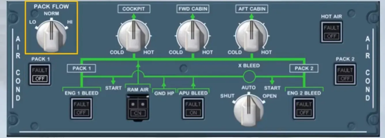
On the overhead panel, the AIR COND panel allows the pilots to control the air conditioning system.
Let’s look at this control in detail.
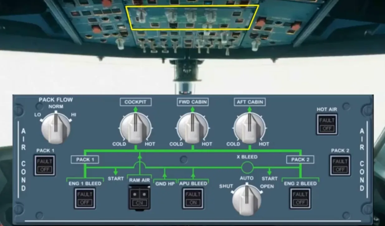
The PACK pushbutton switches control their related pack flow control valves.
In this example:
- Pack 1 pb-sw is selected off, the related valve is closed
- Pack 2 pb-sw is selected on, the related valve is open.
The PACK FLOW sel is used to select the needed pack flow.
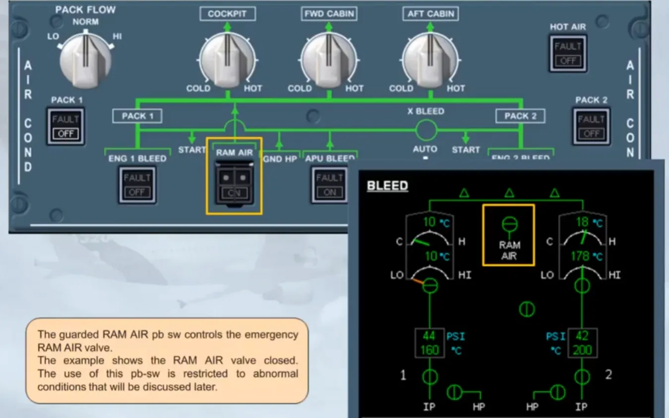
The guarded RAM AIR pb sw controls the emergency RAM AIR valve.
The example shows the RAM AIR valve closed.
The use of this pb-sw is restricted to abnormal conditions that will be discussed later.
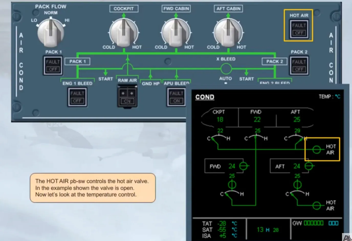
The HOT AIR pb-sw controls the hot air valve. In the example shown the valve is open.
Now let’s look at the temperature control.
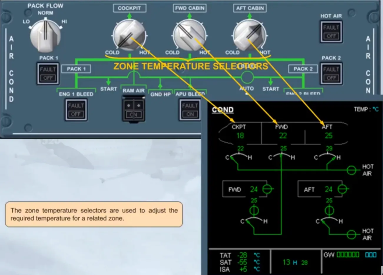
The zone temperature selectors are used to adjust the required temperature for a related zone.
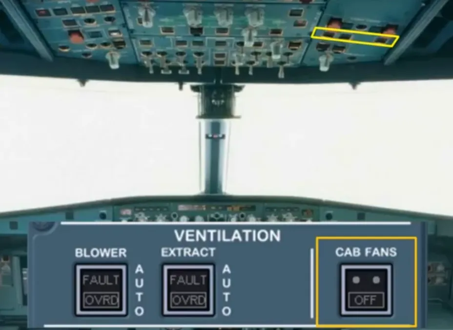
Two cabin fans are installed to recycle cabin air, and therefore save fuel. These fans establish a recirculation flow of air from the three aircraft zones to the mixing unit. In normal operation, there is no ECAM indication related to the cabin fans.
The CAB FANS pb-sw on the VENTILATION panel controls the cabin fans. This pb-sw can be used to switch the fans off in response to ECAM procedure.
Module completed
Video study
Section titled “Video study”- Watch the video available on YouTube