Landing Gear System
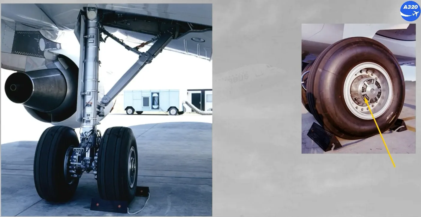
The A320 is equipped with two twin wheel main gear legs which retract inboard …
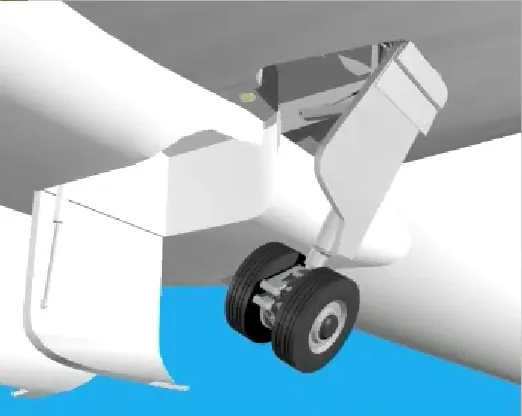
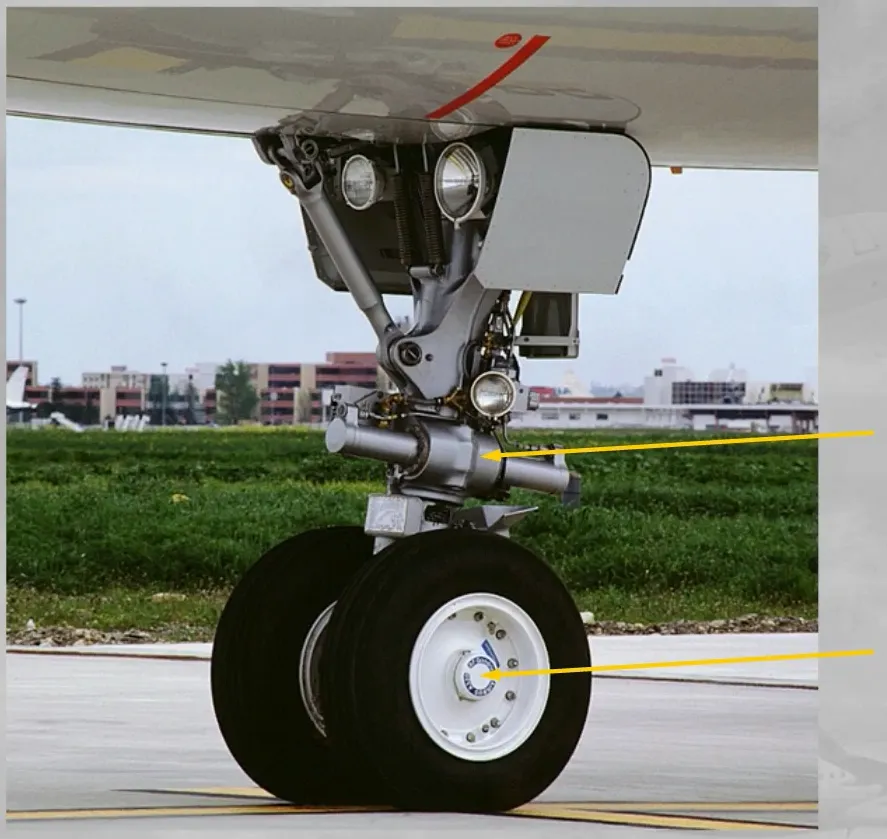
… and a dual wheel nose gear which retracts forward.
The wheels of the main landing gear have carbon multidisc brakes for efficient braking even at high temperature. The brakes are actuated by two independent sets of pistons (NORMAL and ALTERNATE).
Also there are:
- A tachometer for wheel speed indication
- An anti-skid system (A/SKID)
- An automatic brake system (AUTO/BRK)
- Optionally:
- A brake cooling fan
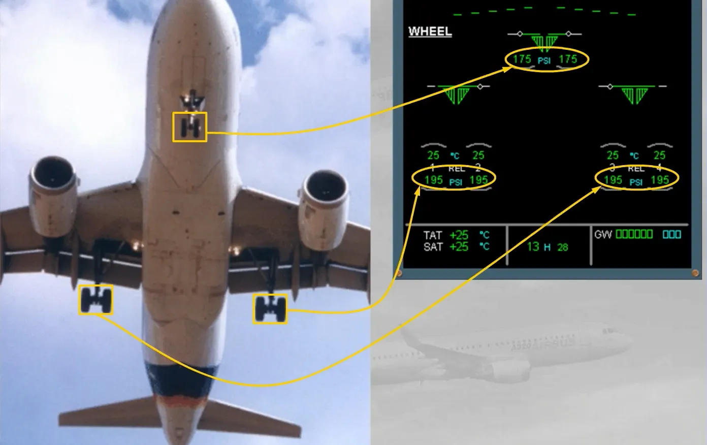
- A Tire Pressure Indicating System (TPIS).
The nose gear is equipped with a nose wheel steering system and the wheels have an option for:
- A Tire Pressure Indicating System (TPIS).
Gear and doors are:
- Electrically controlled
- Hydraulically operated.
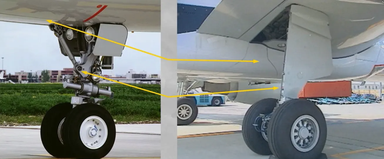
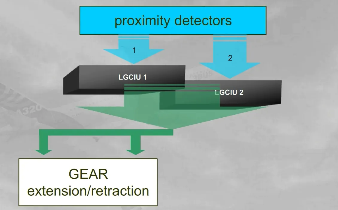
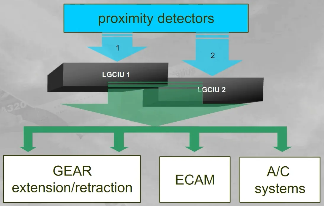
Two Landing Gear Control and Interface Units (LGCIUs) receive information independently from a relative set of proximity detectors, installed on the landing gear and on the cargo doors.
Note: The LGCIUs also receive information from sensors installed on the flaps attachments and send it to the SFCCs (refer to the ATA27-FAILURE CASES module).
A landing gear complete operation (UP and DOWN) is ensured by one LGCIU, the other takes over when the gear cycle ends or if the active LGCIU fails.
The LGCIUs also send proximity detector information to the ECAM and various aircraft systems.
Note: The information, send by a failed proximity detector or a failed LGCIU, will relate to the safe “FLIGHT” condition. Consequently some aircraft system users will wrongly see a “FLIGHT” condition or a “GROUND” condition or a “NOT LOCKED” condition.
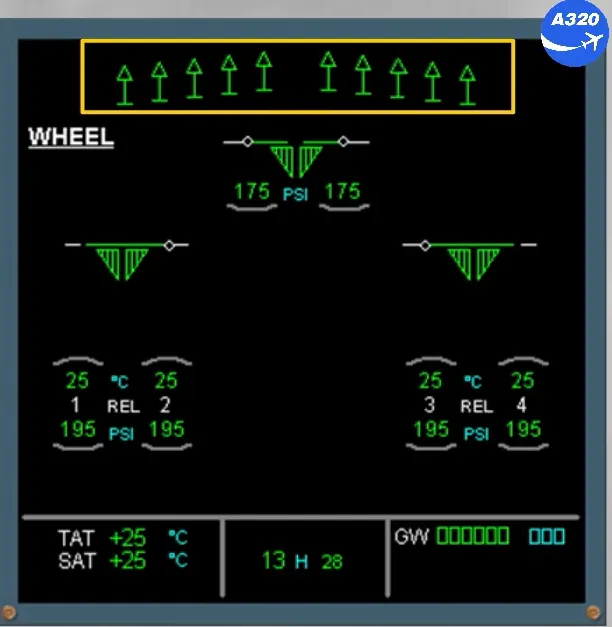
The ECAM WHEEL page displays indications for:
- The main landing gear and the nose landing gear
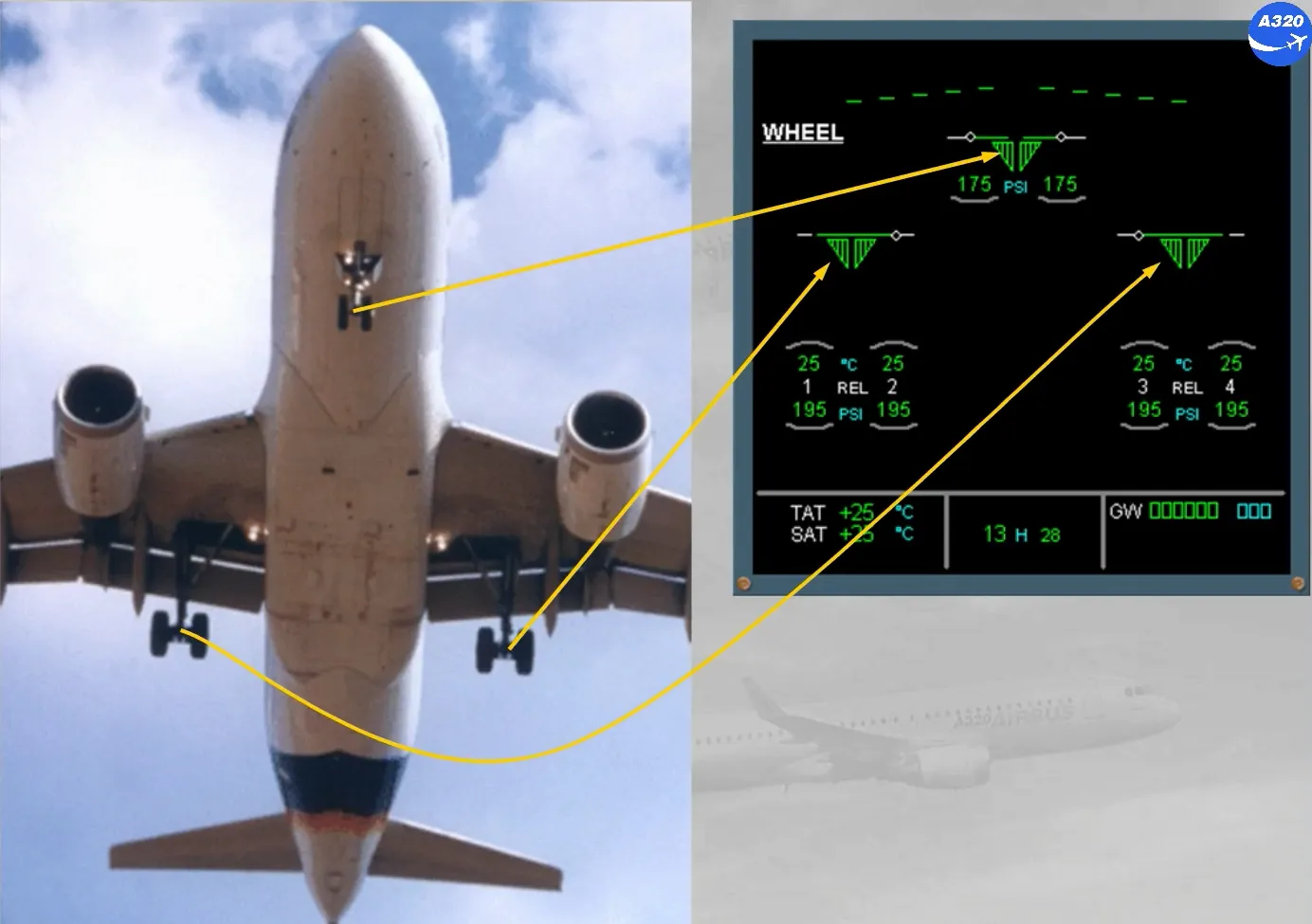
- Their related doors
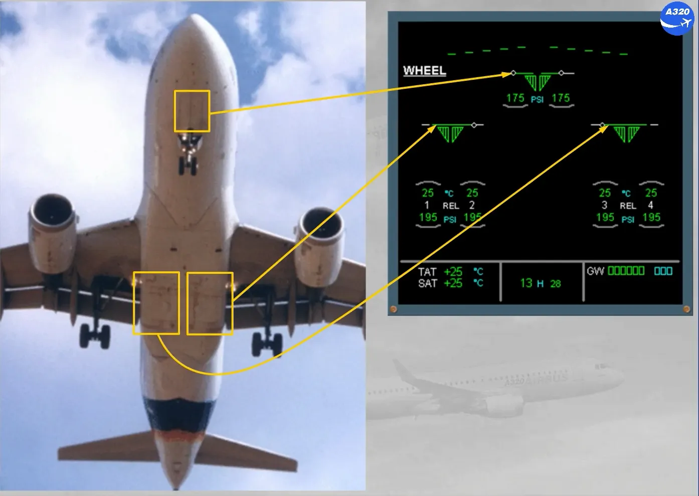
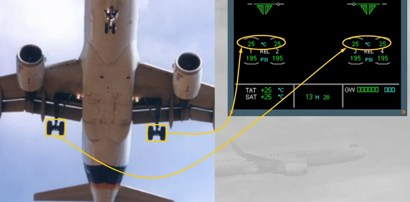
- The brake temperatures, and…
- … Optionally the tire pressures.
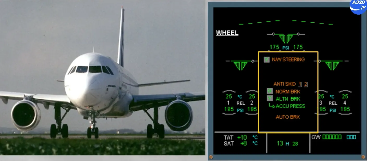
In the center of the ECAM WHEEL page, green and amber messages can be displayed to provide normal and abnormal indications.
This will be discussed further in the FAILURE CASES module.
At the top of the ECAM WHEEL page, the position of the spoilers is displayed.
This will be discussed in the FLIGHT CONTROLS chapter.
Let’s go to the cockpit to locate the controls and indicators for the landing gear, steering and brakes.
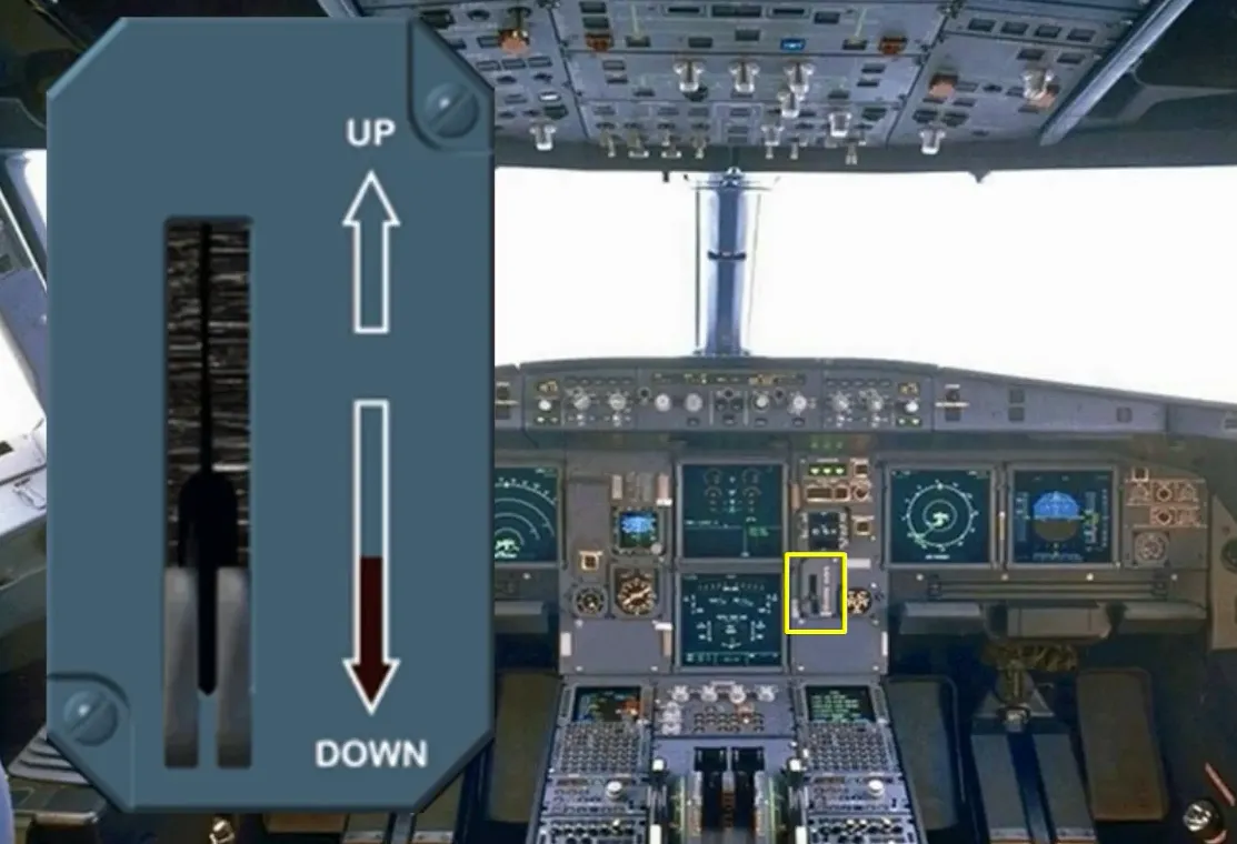
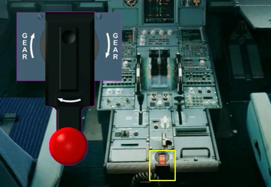
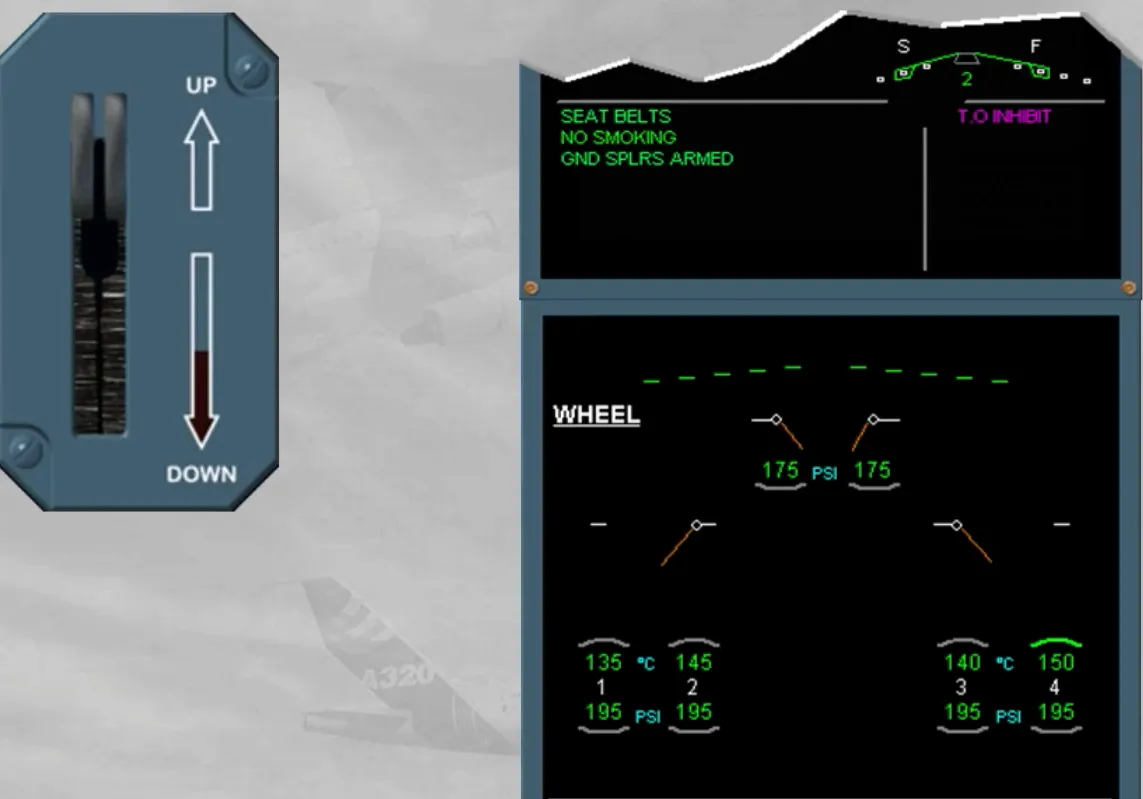
The landing gear selector lever is located on the center instrument panel. This lever will send UP or DN orders to the LGCIUs, which in turn sequence the gears and doors. They will move hydraulically to the selected position provided the airspeed is below 260 knots.
Note: when UP is selected, the main wheels are braked, while then doors open.
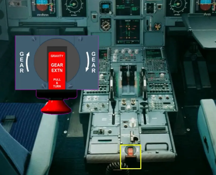
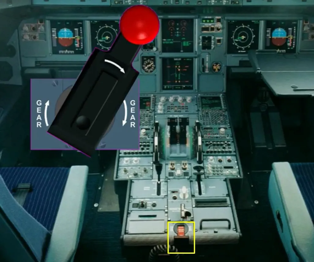
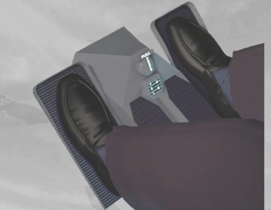
The landing gear gravity extension handle is located on the center pedestal. When it is turned clockwise until the stop, the gears and doors are hydraulically depressurized, and mechanically unlocked. The main gears will lock down assisted by spring forces and the nose gear by aerodynamic forces.
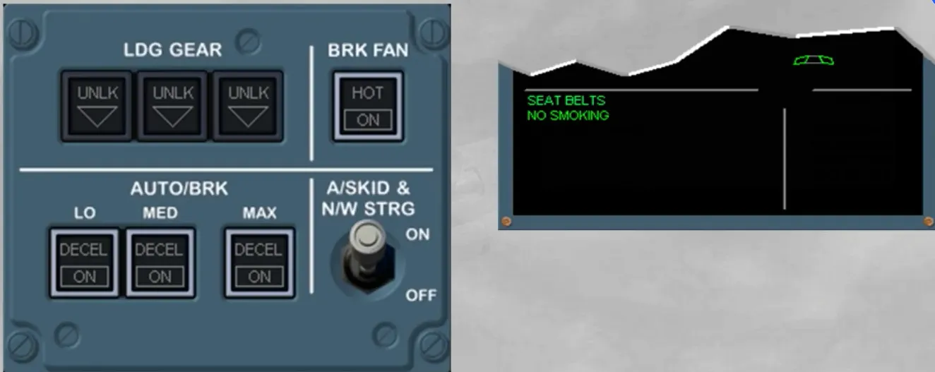
Just above the landing gear lever is a panel which contains switches and indicators for:
- The LDG GEAR
- The AUTO/BRK
- The BRK FAN
- The A/SKID & N/W STRG.
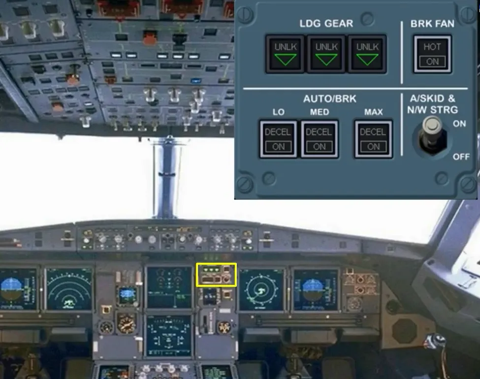
Let’s take a closer look.
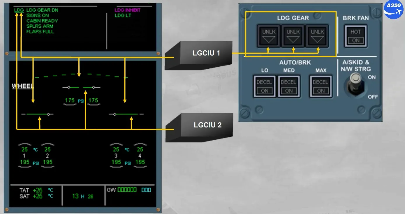
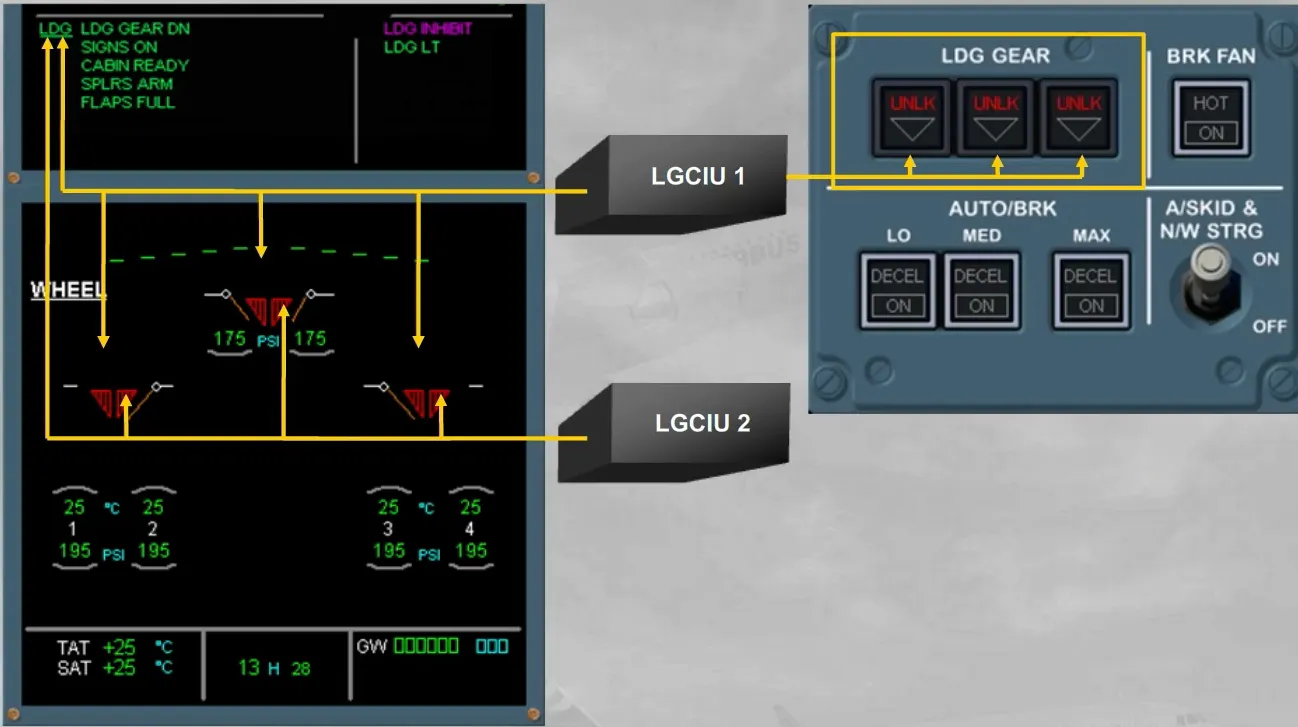
The LGCIUs provide the landing gear position indications:
- To the LDG GEAR panel, from the LGCIU 1 only
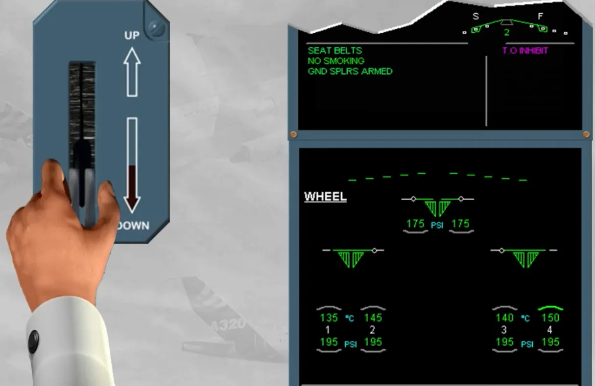
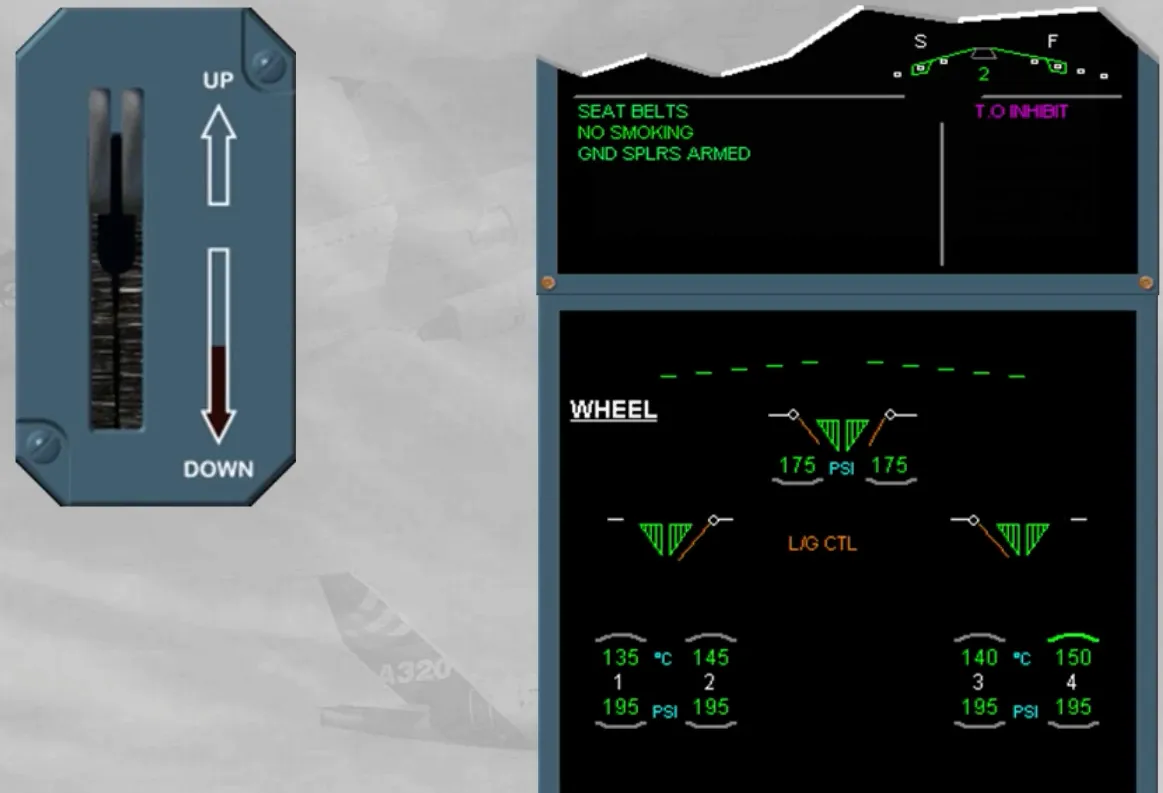
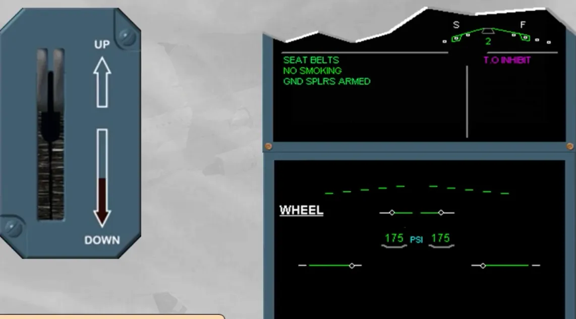
- To the WHEEL page and the LDG memo, from both LGCIUs. Notice the indications when the landing gear is UP, in transit and DN.
Note: Due to the efficiency of the proximity detector type, only one LGCIU indication is sufficient to confirm that the gear is correctly UP or DN. In that case, any warning activation, must be considered as wrong, ECAM message must be disregarded and cancelled.
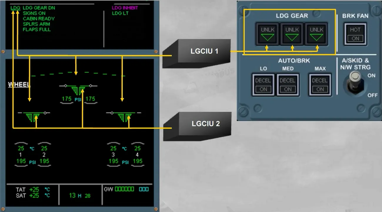
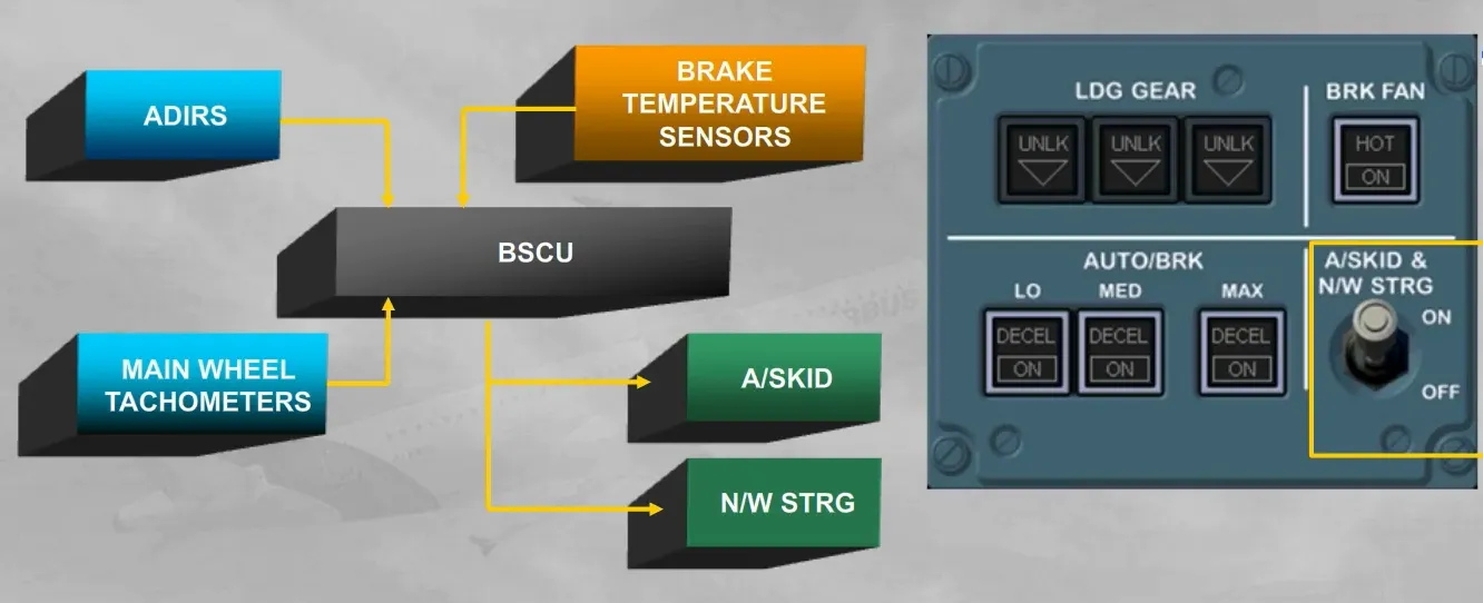
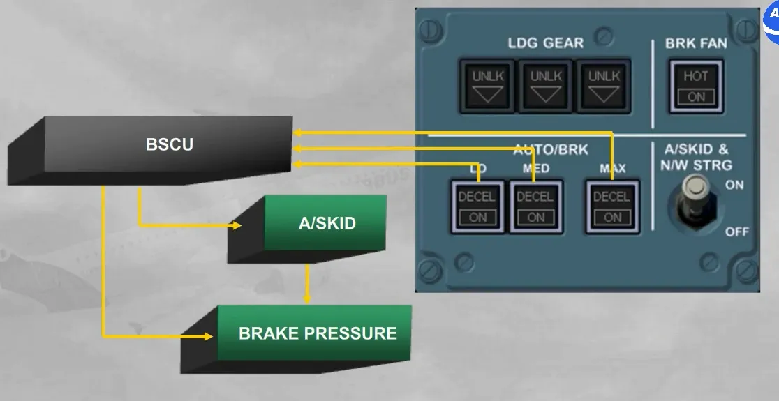
The A/SKID & N/W STRG switch allows the Brake and Steering Control Unit (BSCU):
- To control the anti-skid and the steering functions
- To monitor the brake temperatures
- To compare the speed from the ADIRS with the wheel speed from the tachometers, used by the anti-skid function for brake release orders.
The switch is normally left in the ON position.
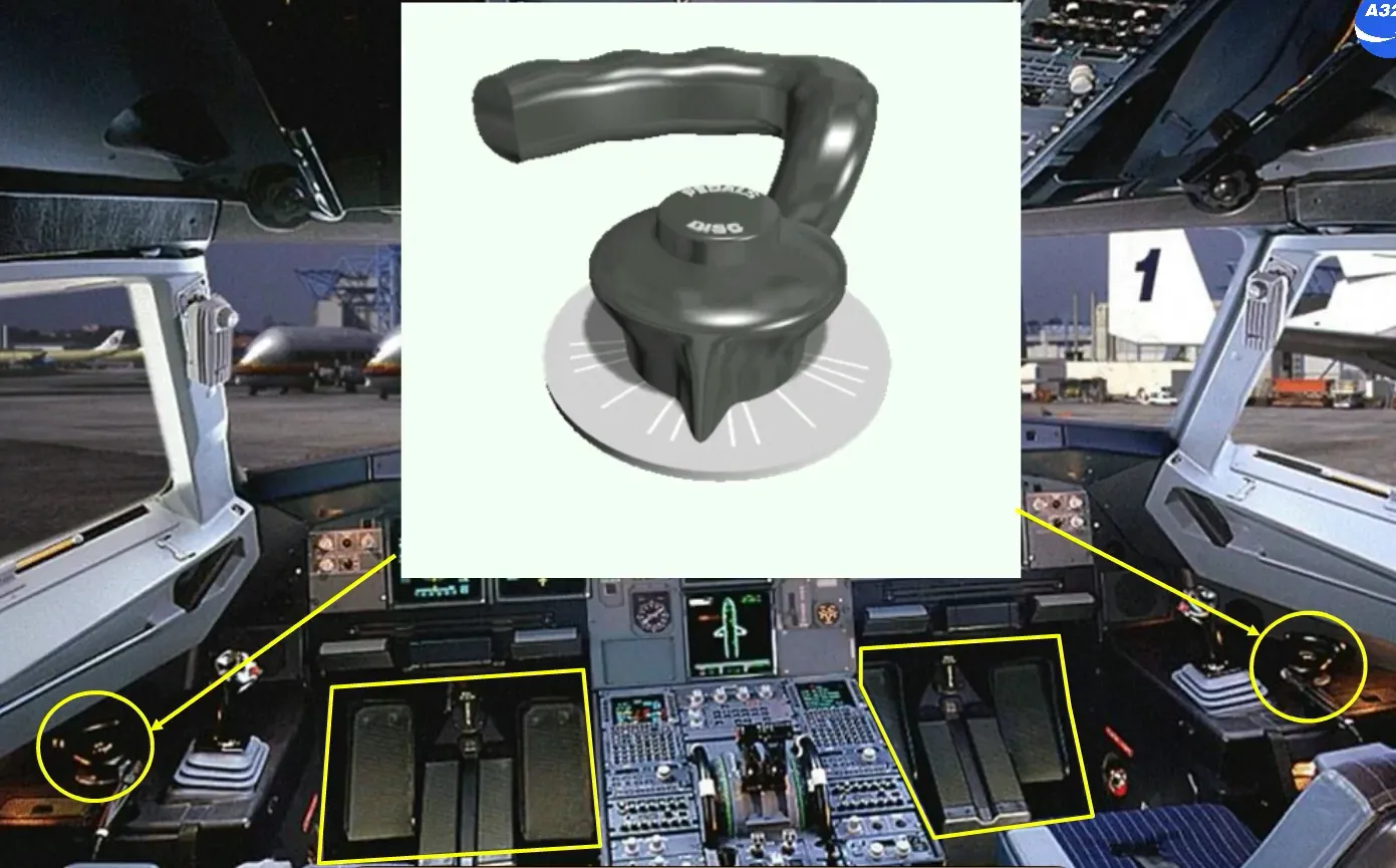
A steering handwheel is located on each side of the cockpit, so either pilot can taxi the aircraft.
The rudder pedals can also be used to steer the aircraft.
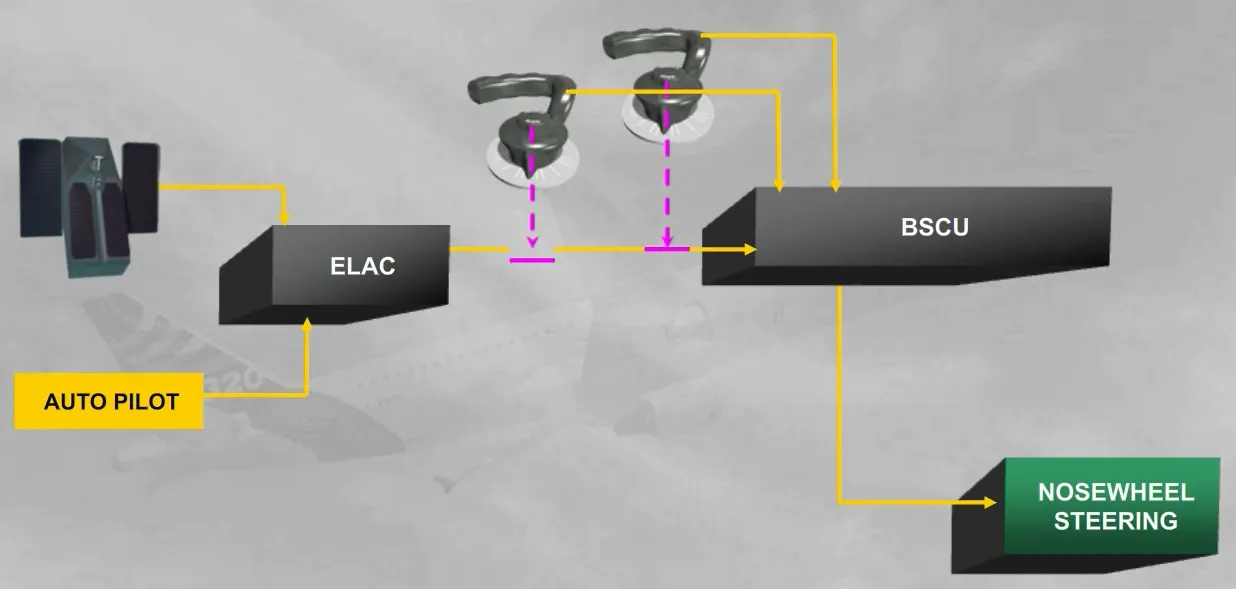
For the steering control, the BSCU receives orders:
- From the pilot handwheels
- From the rudder pedals and the autopilot, via the ELevator Aileron Computer (ELAC).
Note: the BSCU will add algebraically each handwheel and ELAC orders. So a rudder pedal disconnect push button can be used during taxi to provide full authority to the handwheel.
Also, the rudder pedal and the handwheel orders are limited depending on the ground speed (refer to your documentation for more details).
The AUTO BRK part allows the BSCU to adjust the braking pressure according:
- To the selected mode (LO, MED or MAX)
- To the anti-skid release orders.
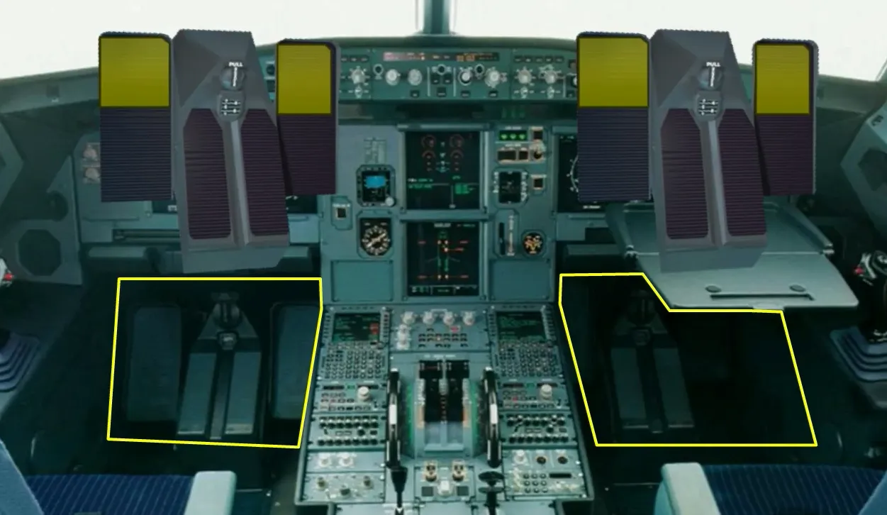
Manual braking is provided using the top of the rudder pedals.
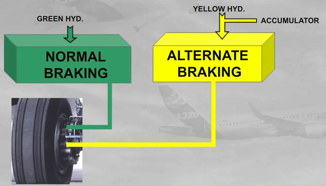
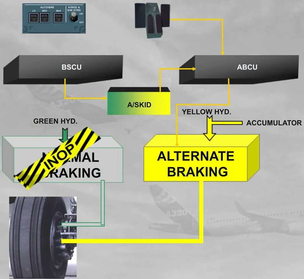
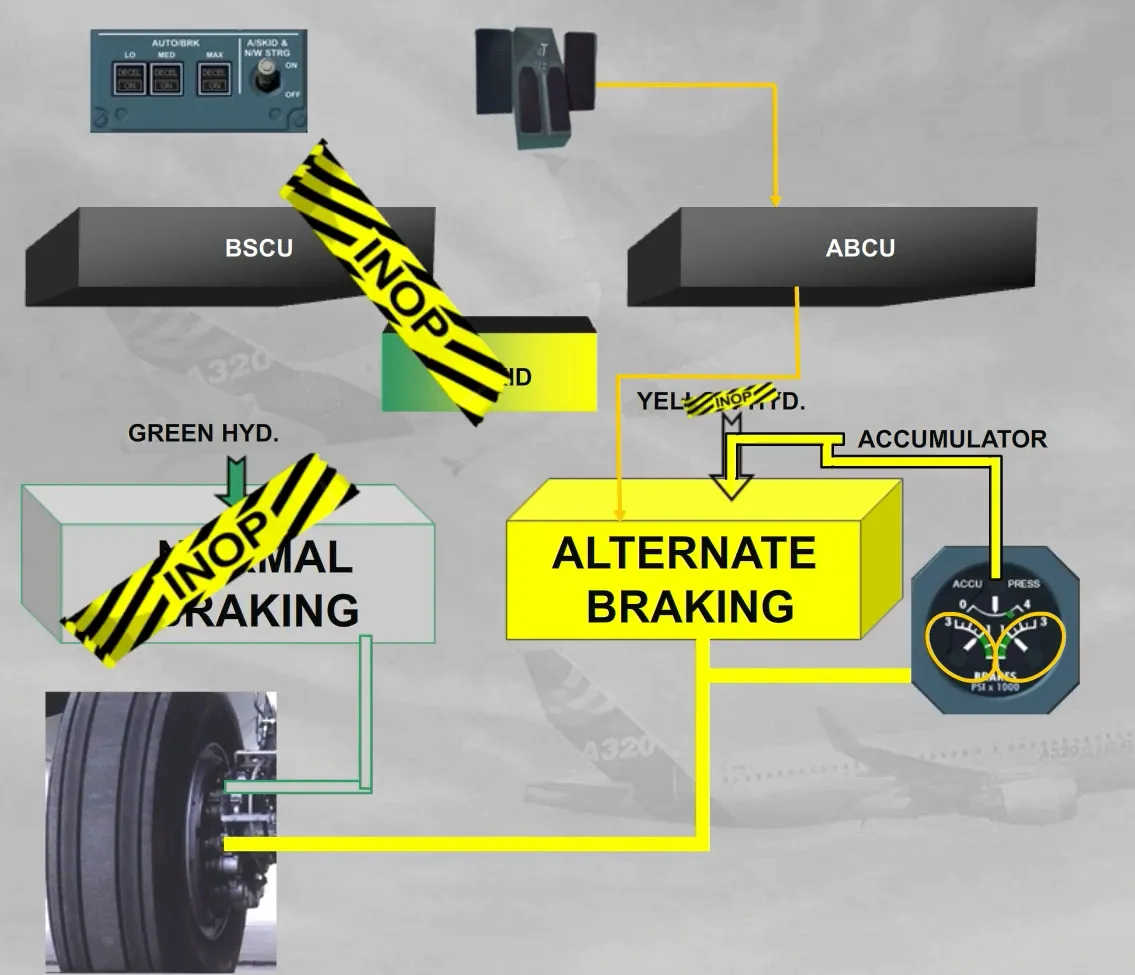
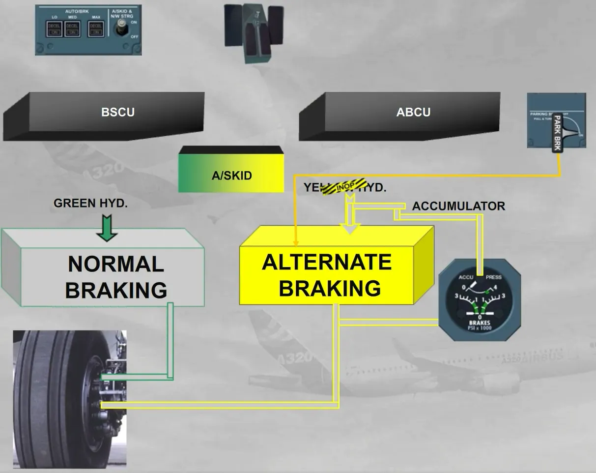
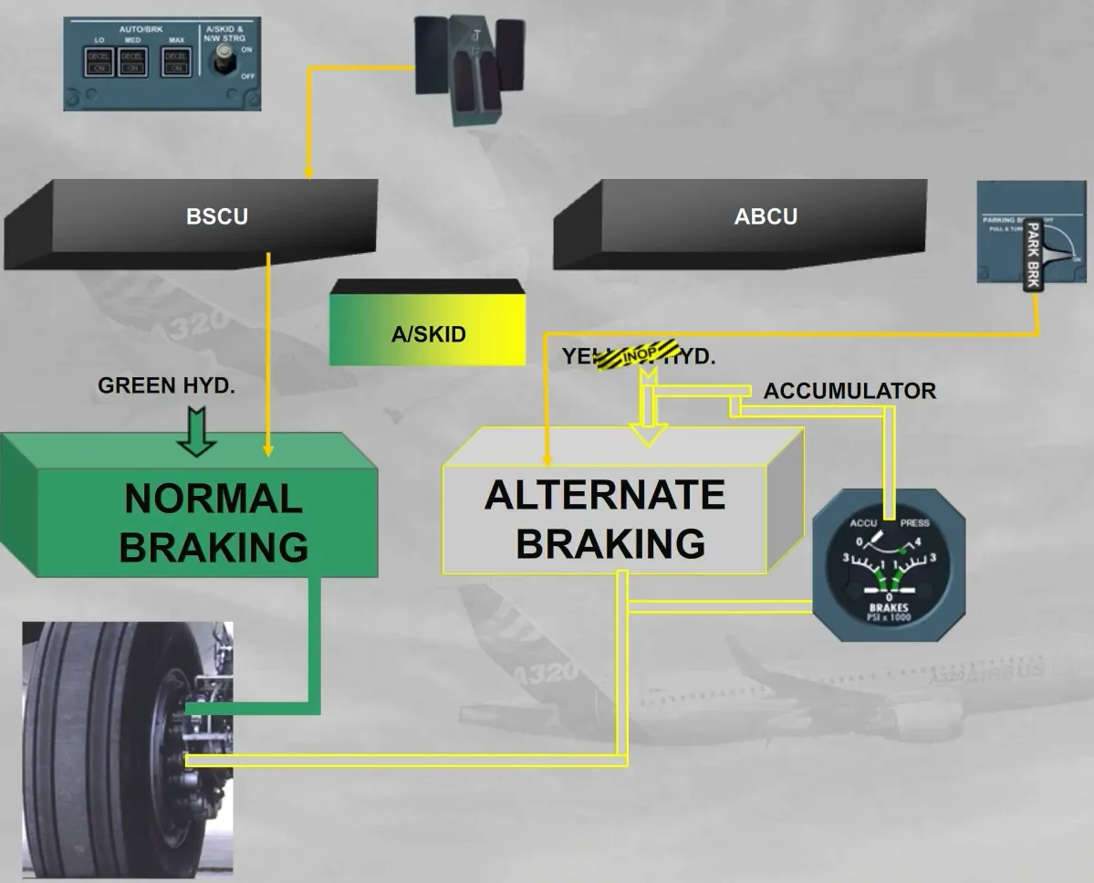
There are two independent braking systems:
- The normal braking using the pressure delivered by the green hydraulic circuit
- The alternate braking using the pressure delivered by the yellow hydraulic circuit or by the accumulator.
The normal braking is controlled by the BSCU, which uses braking orders from the AUTO BRAKE system or from the brake pedals. The normal braking orders are also protected by the anti-skid.
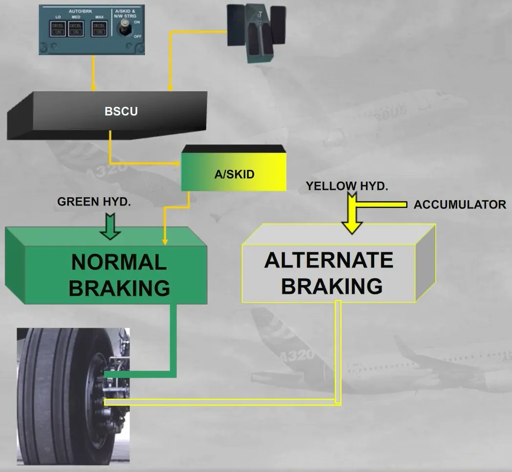
When the normal braking is not available, the alternate braking is automatically activated and is controlled by an Alternate Braking Control Unit (ABCU), which uses the braking orders from the brake pedals. Also the antiskid protection will be available if the BSCU is sill available.
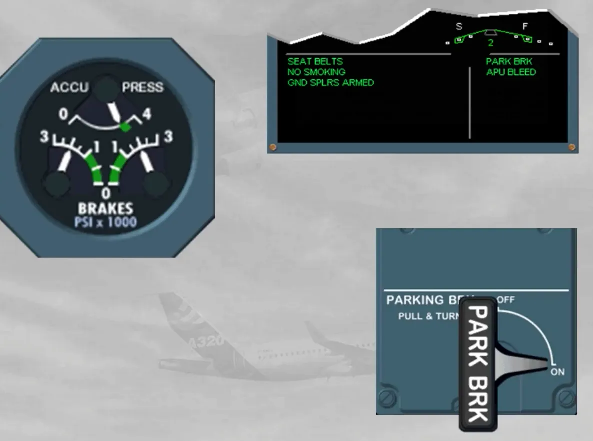
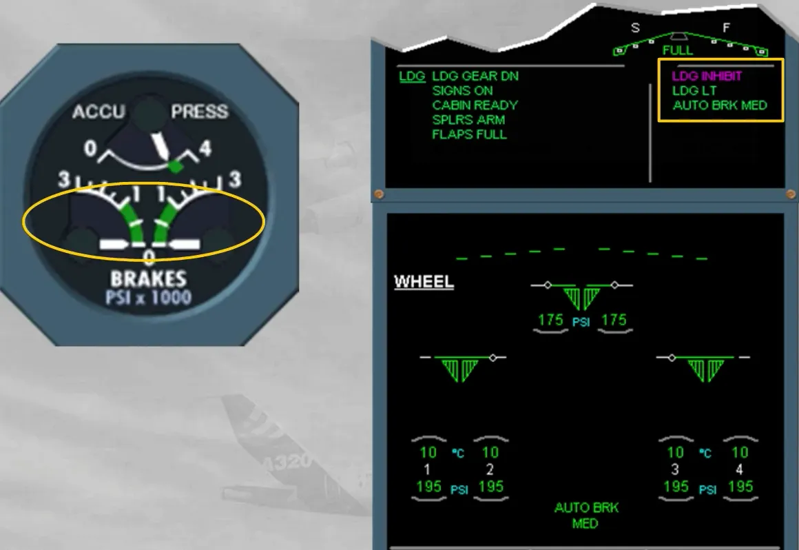
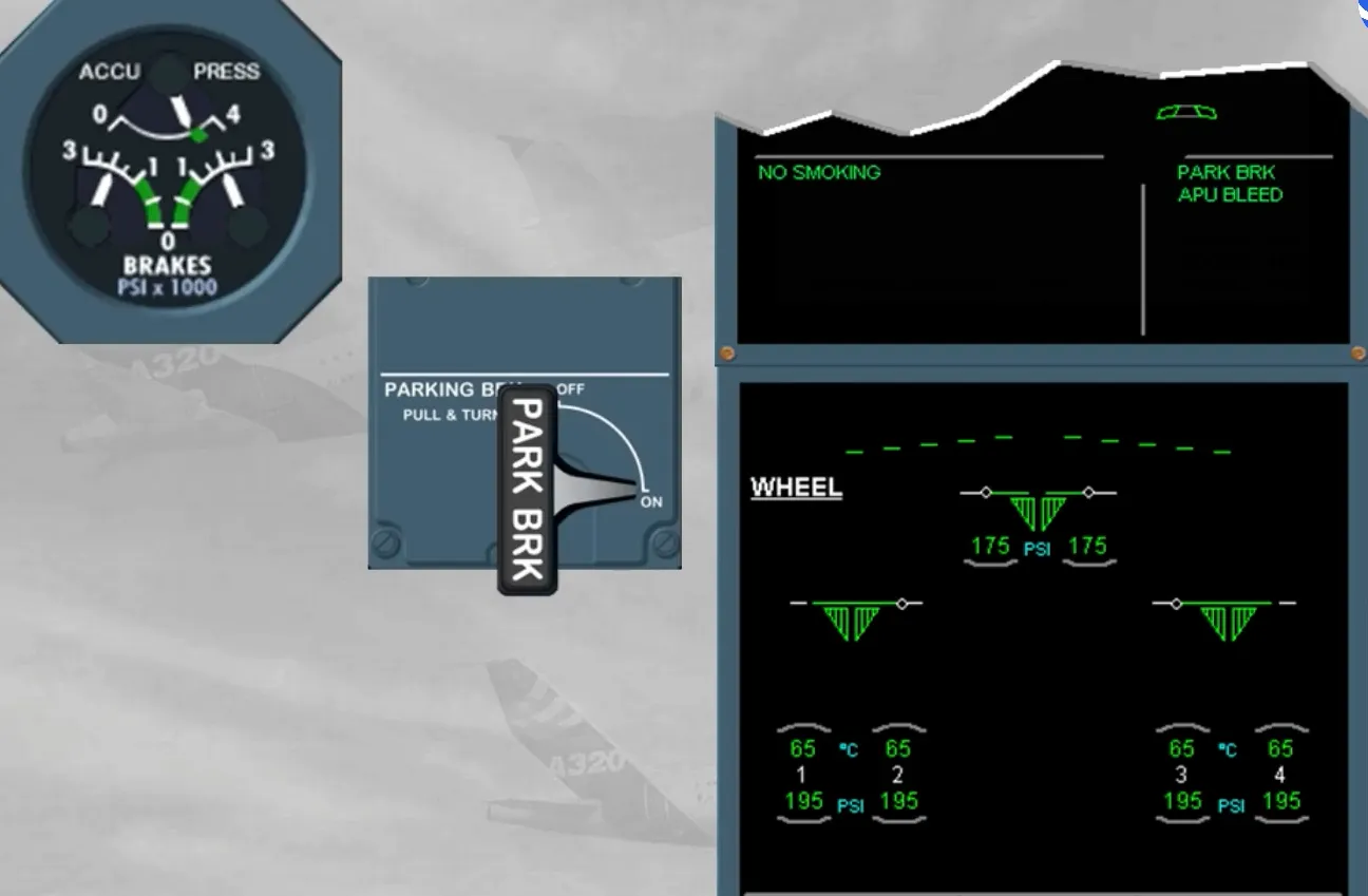
An ACCU PRESS & BRAKES indicator is located on the main instrument panel.
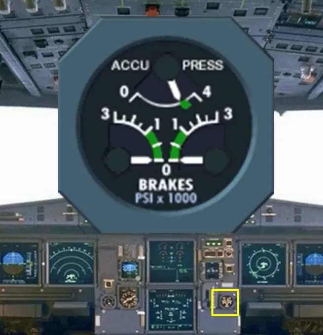
This gage indicates:
- The left and right braking pressures from only the alternate braking system
- The pressure of the accumulator which is permanently maintained charged by the yellow hydraulic circuit.
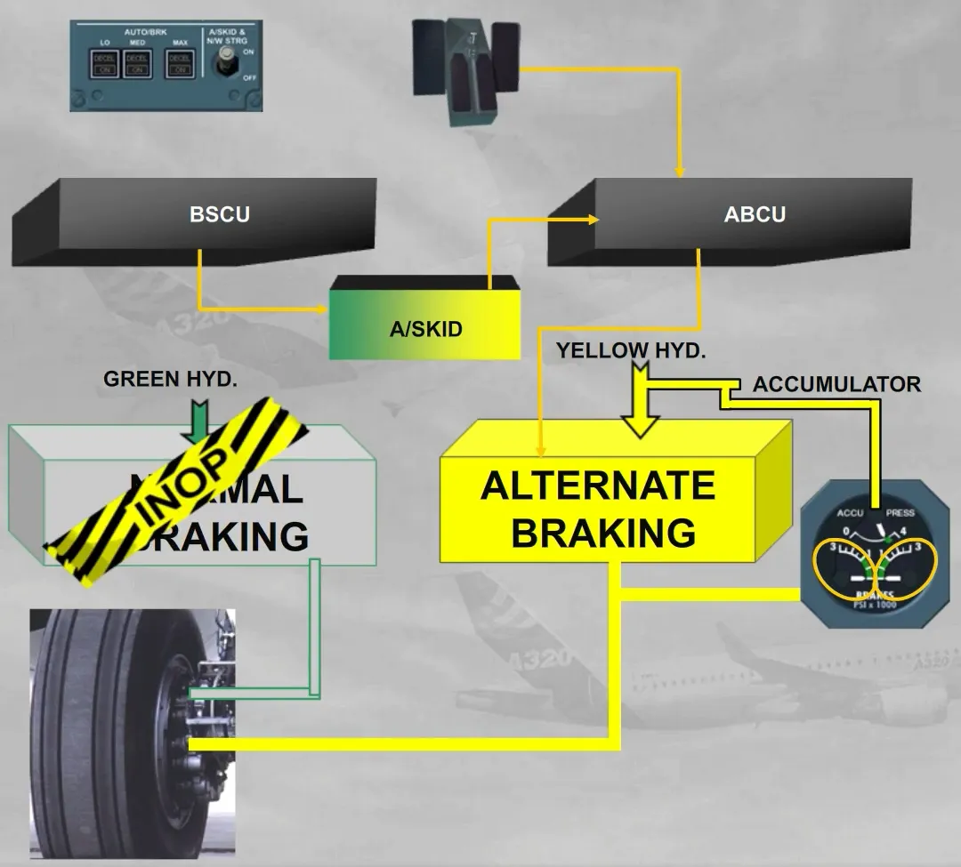
If the antiskid protection is not available, the ABCU controls the alternate braking which uses the braking orders from the brake pedals. During braking operation, the pilots should not exceed the green sector, even if the ABCU has automatically limited the braking pressure at 1000 PSI.
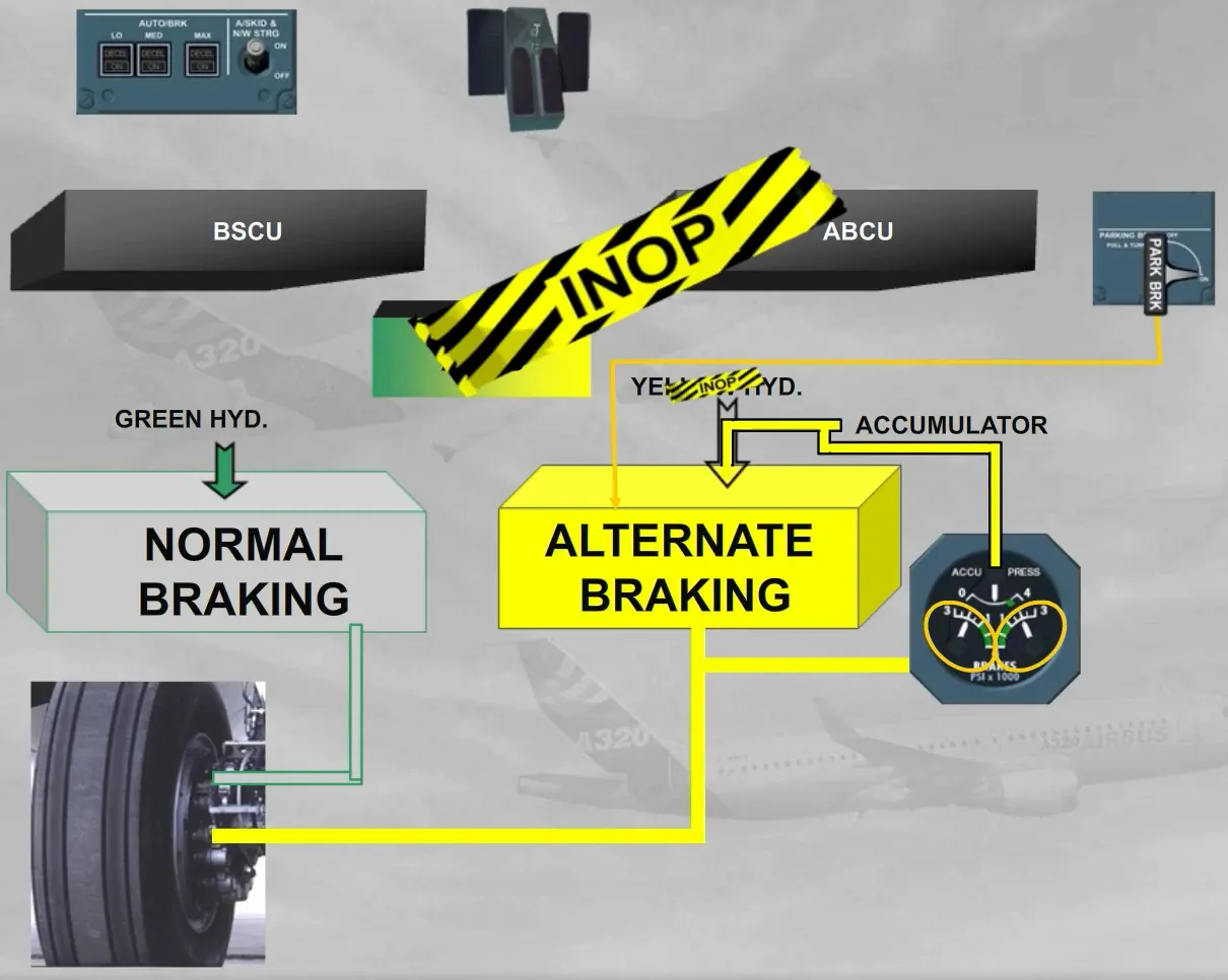
If the yellow hydraulic circuit is not available, the accumulator is automatically used, and the ABCU controls the alternate braking which uses the braking orders from the brake pedals.
During braking operation, the pilots should not exceed the green sector, even if the ABCU has automatically limited the braking pressure at 1000 PSI. The accumulator is designed to supply at least seven full brake applications.
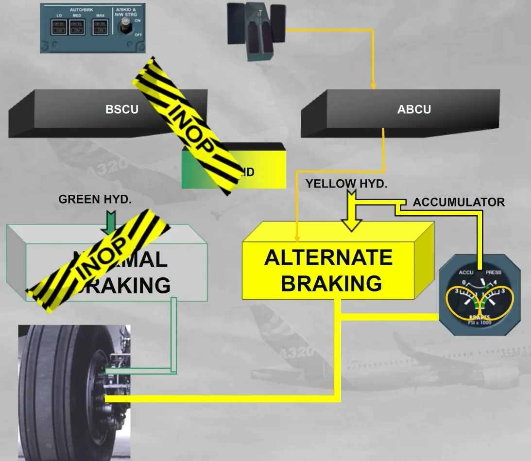
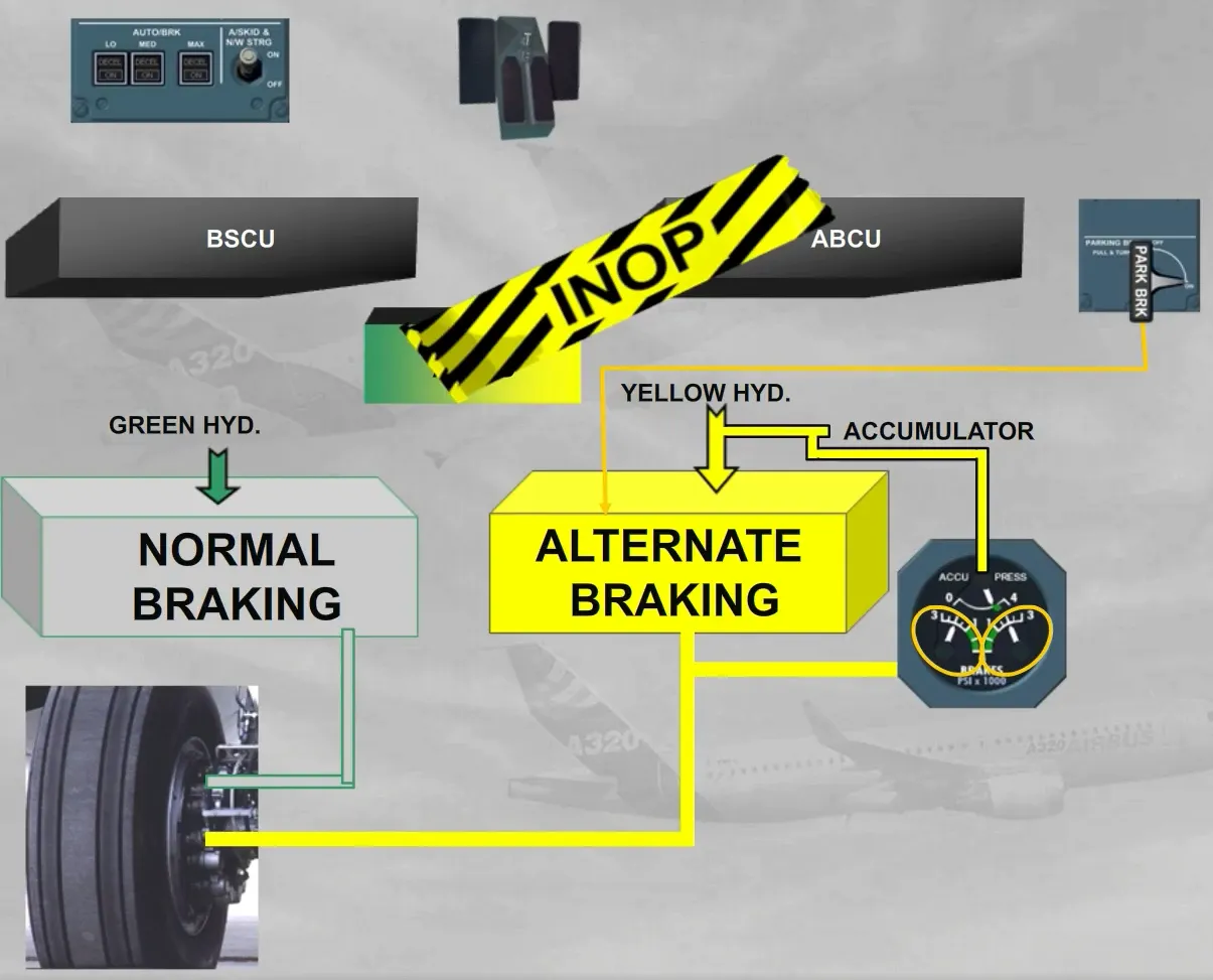
The parking brake handle is located on the center pedestal.
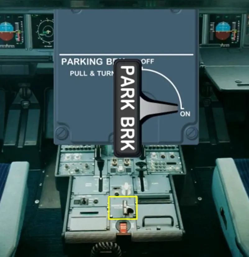
When the parking brake is used, the ABCU and the A/SKID orders are inoperative. A non modulated braking pressure is applied on the left and right brakes of the alternate braking system.
If the yellow hydraulic circuit is not available, the accumulator allows the braking pressure to be maintained for around 12 hours.
With the parking brake applied from only the accumulator pressure and with the green hydraulic circuit available, if the brake pedals are used, the normal braking system is immediately activated. This allows the aircraft to be stopped in emergency, if the parking brake pressure is not sufficient to hold it.
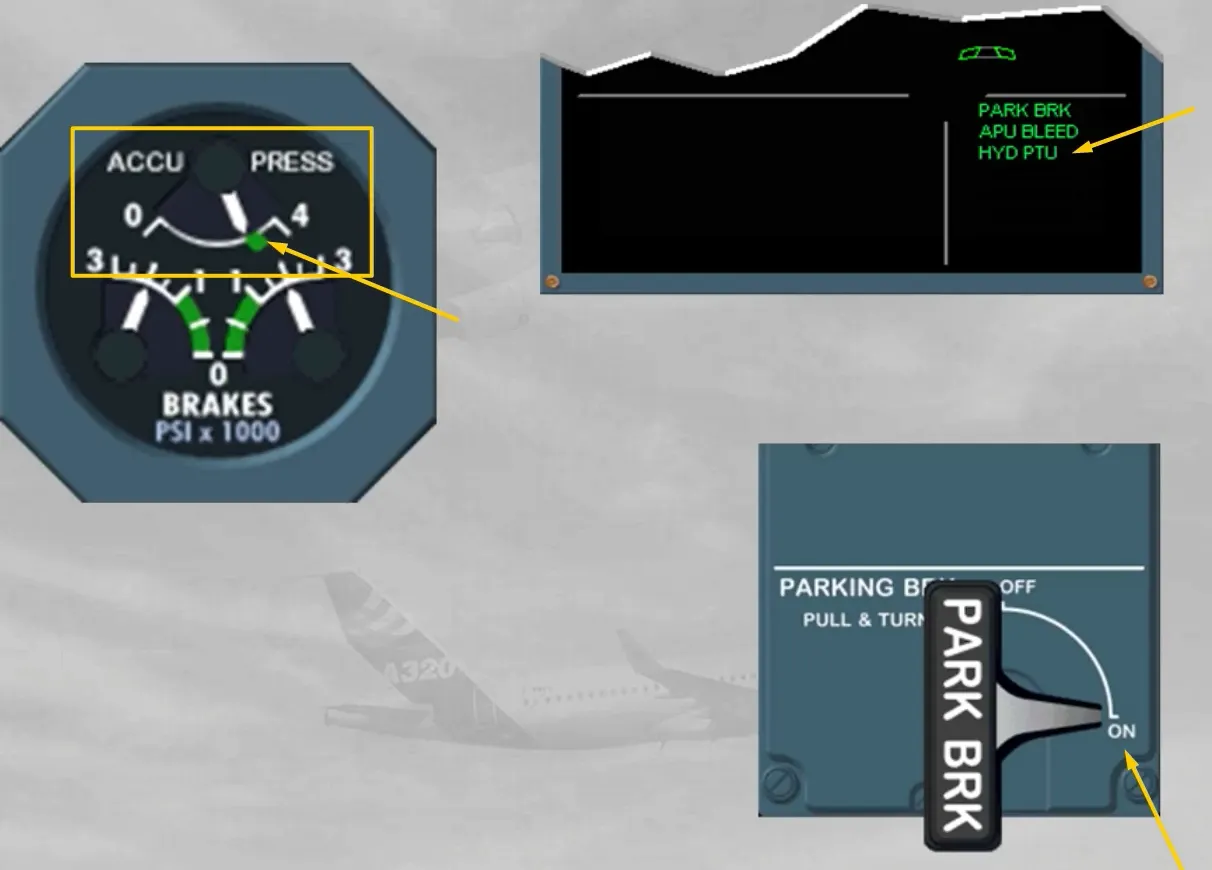
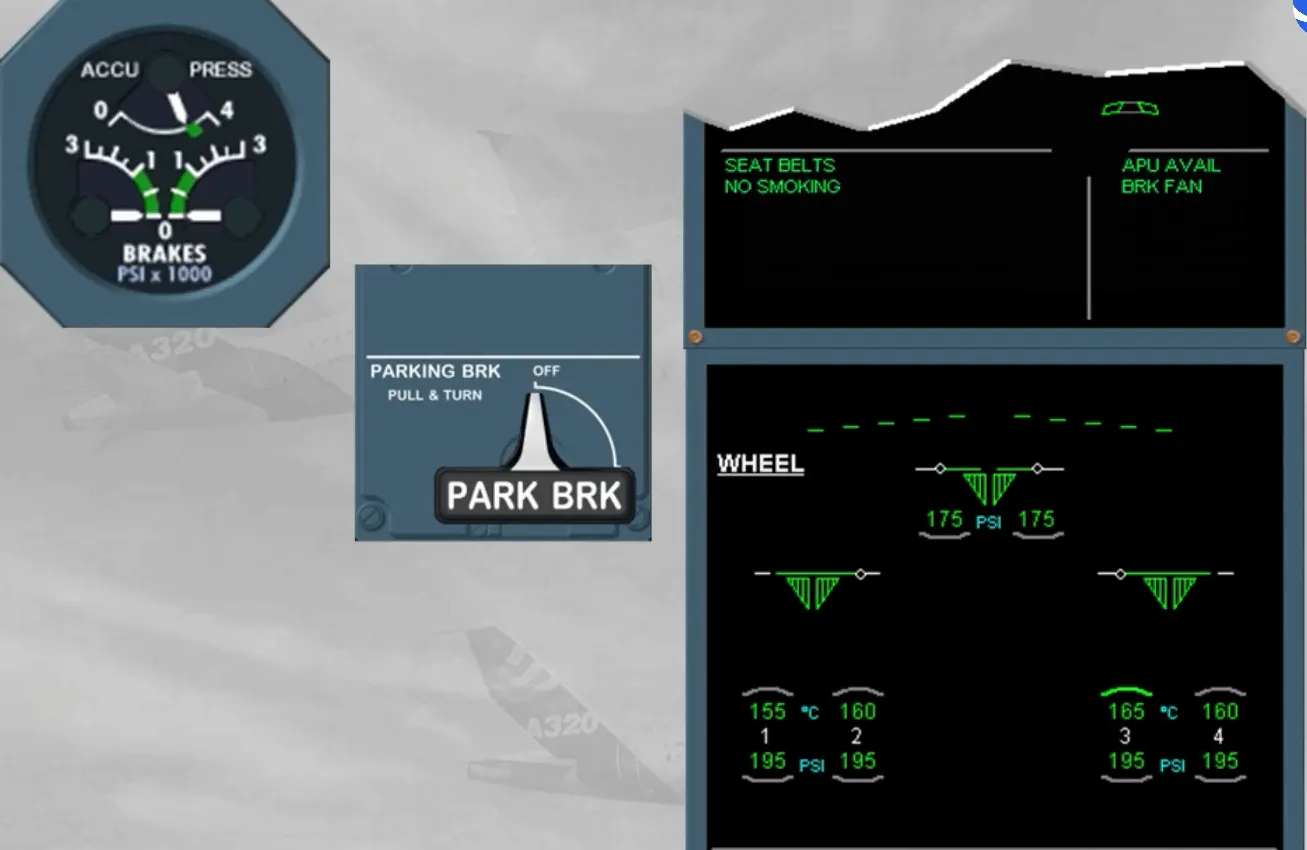
During the preliminary cockpit preparation, and after having set the PARKING BRK to ON, you have to check the ACCU PRESS & BRAKES indicator for normal indications.
The ACCU PRESS indication must be in the green area. If not, the yellow electric pump can be used to recharge the accumulator.
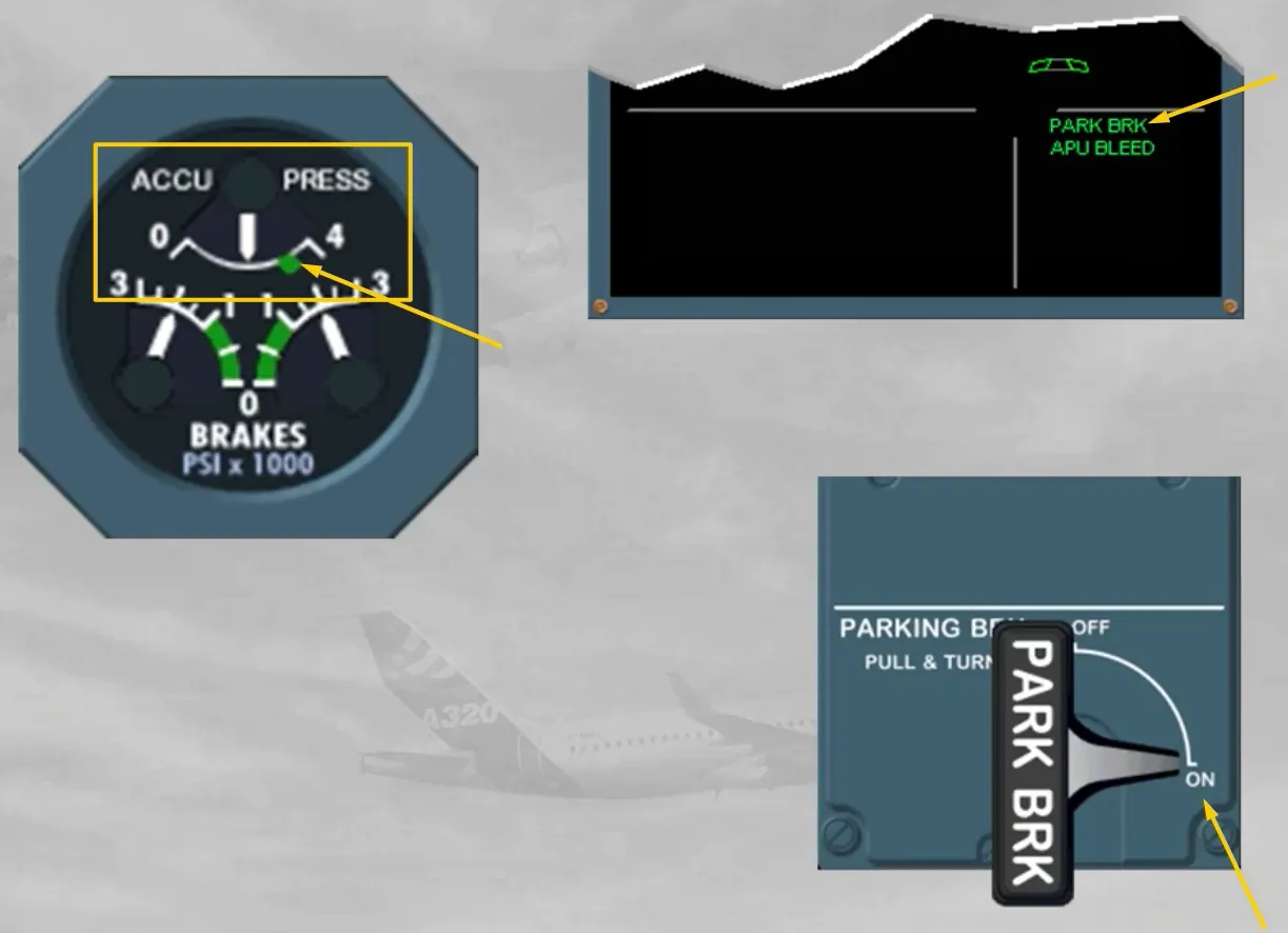
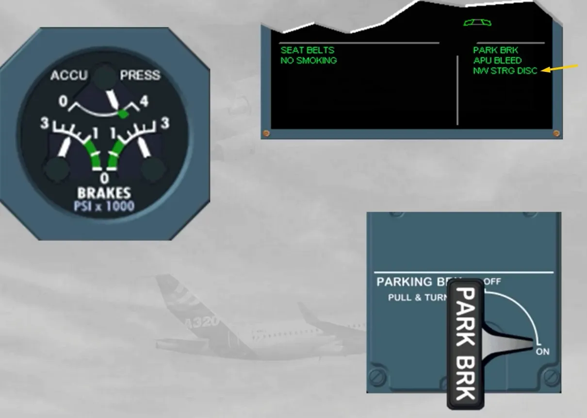
Before pushback the nosewheel steering selector bypass pin must be in the TOW position. This deactivates electrically the nosewheel steering hydaulic actuator, which is confirmed by a memo message, as shown.
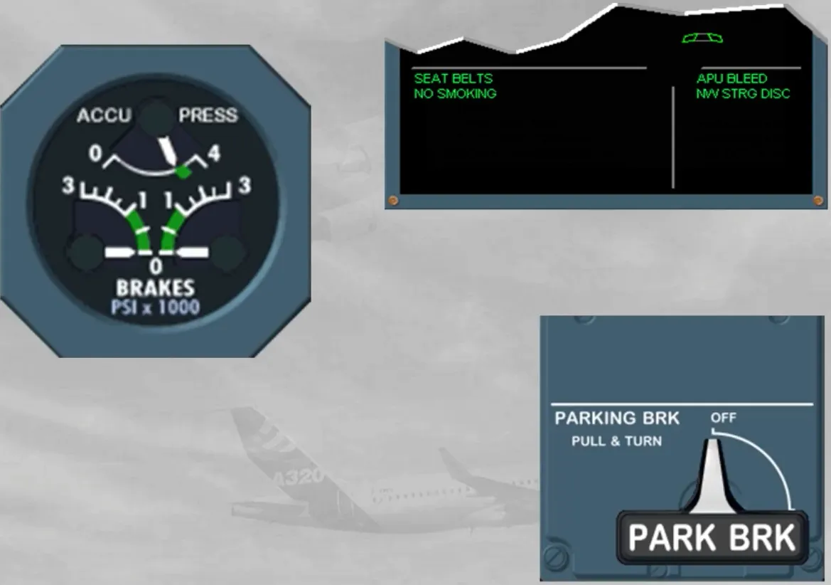
When pushback is required, the PARKING BRK must be released.
Note: in case of powerpush by the main landing gear, the nosewheel steering must be kept connected and the handwheel will be used for steering the aircraft.
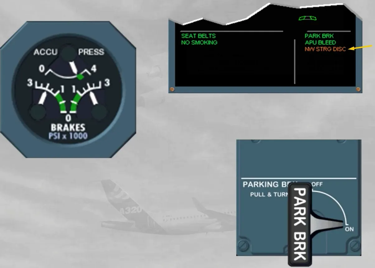
When pushback is completed, the PARKING BRK must be set to ON.
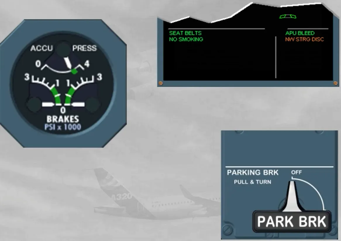
Note: The NW STRG DISC message has turned to amber because at least one engine is running.
Then you should request to remove the nosewheel steering bypass pin.
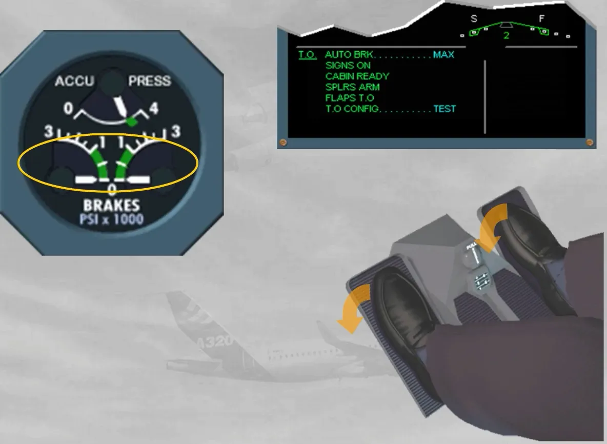
For taxiing, you have to check that the parking brake pressure has dropped to zero. Then, as soon as the airplane is moving, the brake pedals must be used. So the airplane should slow down. This confirms the brake efficiency of the normal braking system, if no brake pressure indication is shown on the indicator.
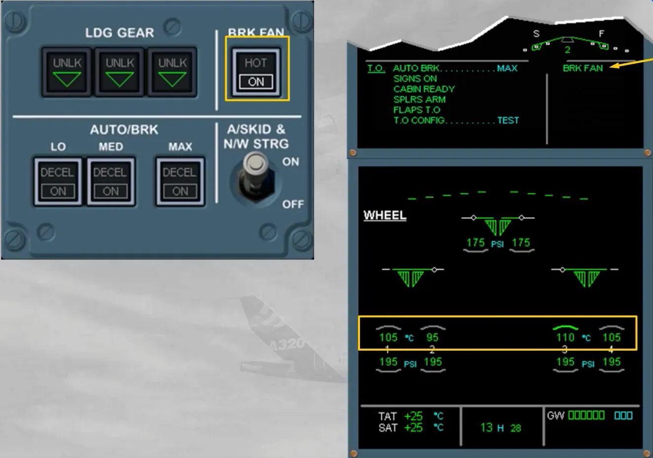
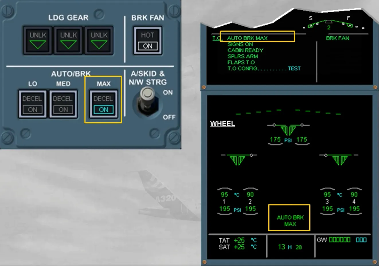
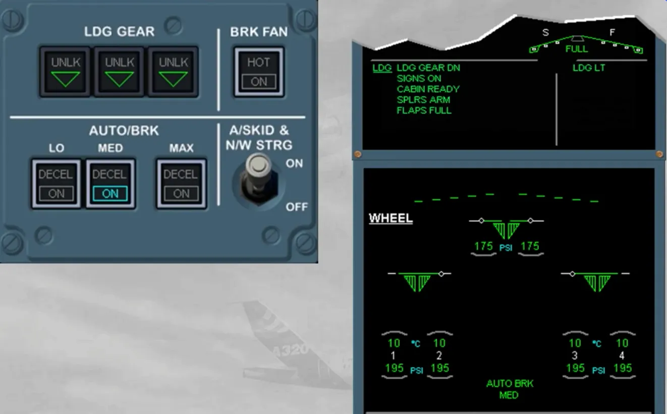
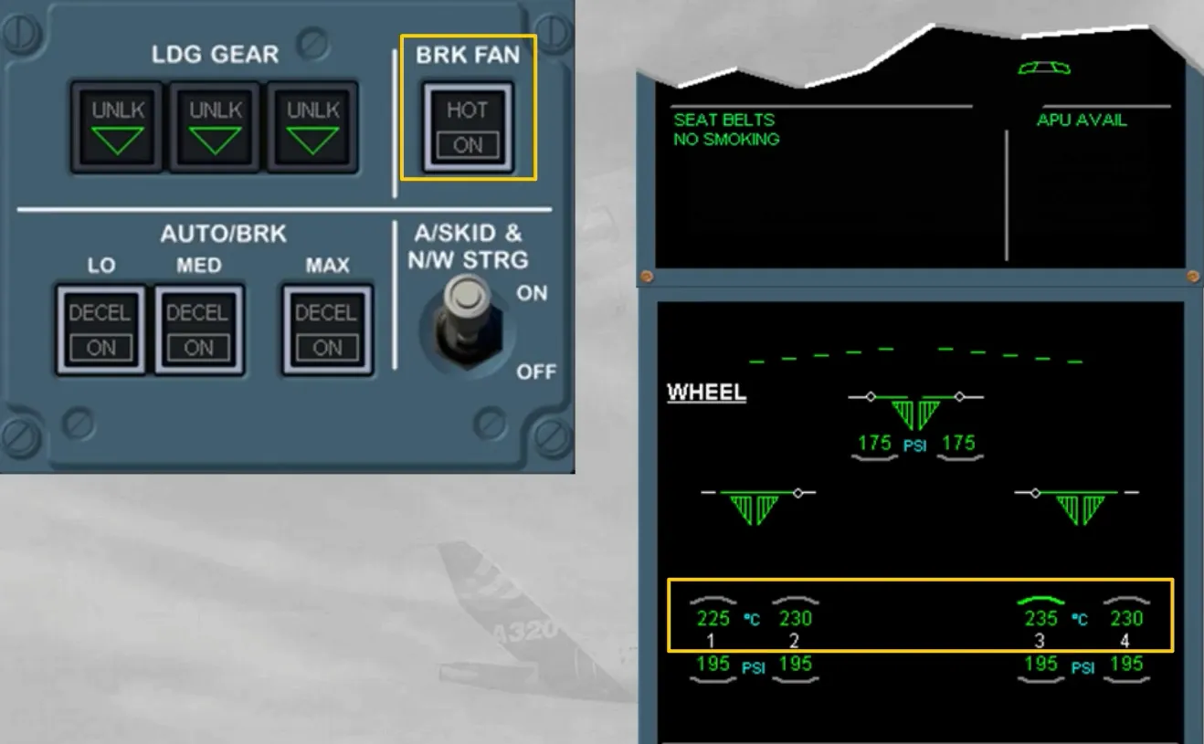
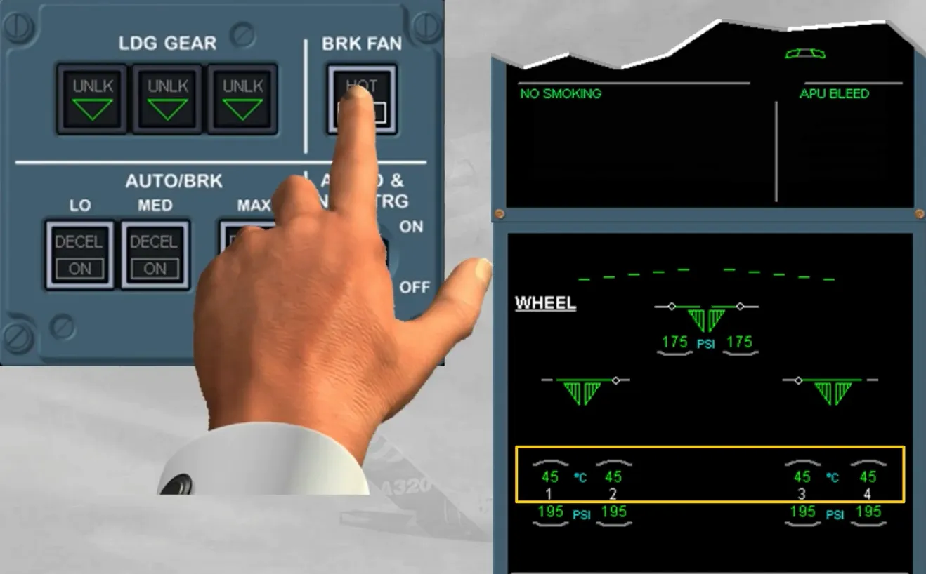
During taxi, the brake temperature must be monitored on the WHEEL page, which is the defaulted SD page for this ECAM phase. If an arc appears above the hottest brake temperature (exceeding 100℃), the BRK FAN pb-sw (if installed) may be set to ON.
Note: The brake fans, when ON, are running as long as the left main landing gear is down and locked.

Also the AUTO BRK must be armed at MAX. Selecting MAX before takeoff improves safety, because in case of rejected takeoff, it ensures the maximum braking pressure as soon as the ground spoiler deployment order has been generated (refer to the FLIGHT CONTROLS chapter).
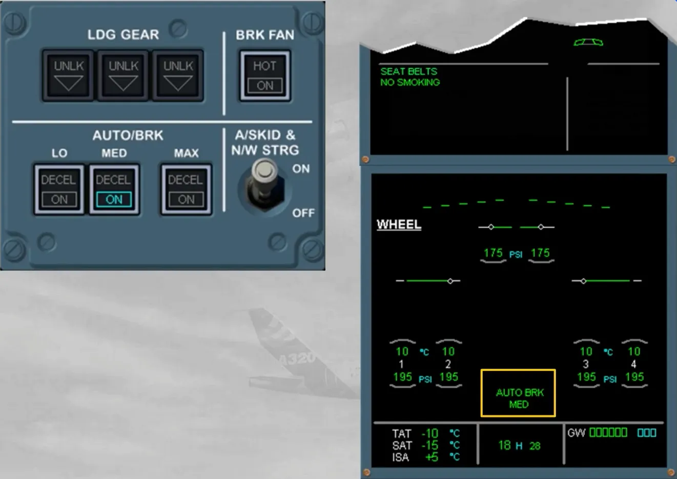
The autobrake arming indications are:
- On the related mode pb-sw, a blue ON light is on
- On the ECAM WHEEL page a green message with the related selected mode is displayed
- On the E/WD, the related blue item has turned to green on the T.O MEMO.
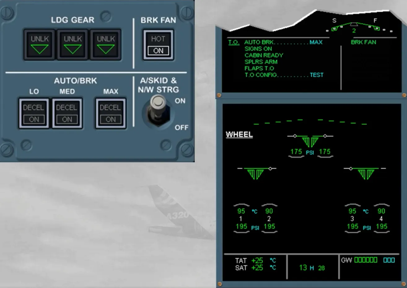
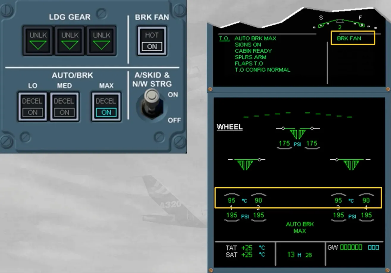
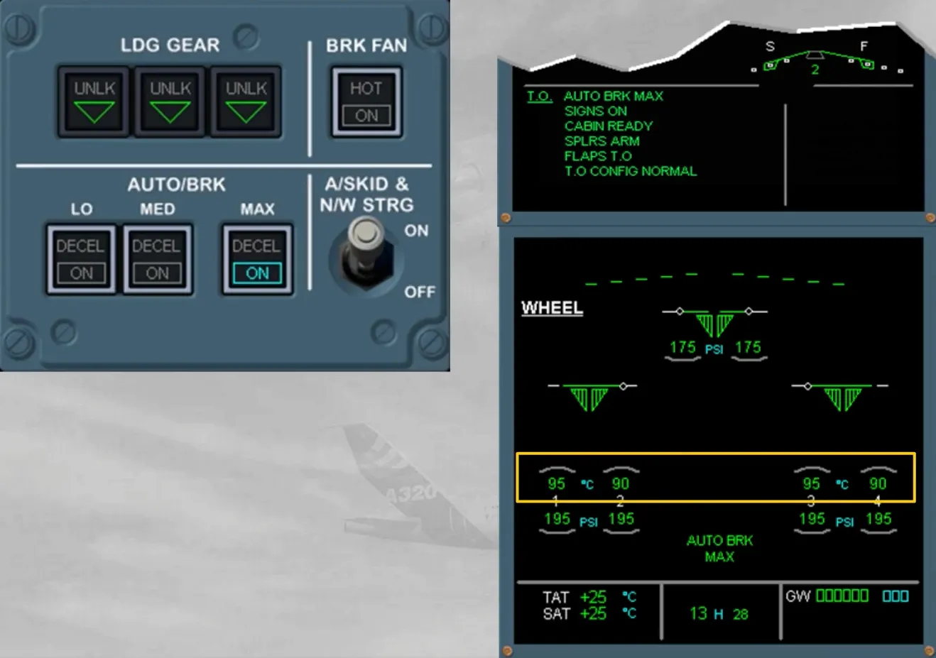
Before takeoff, the brake temperature must be checked.
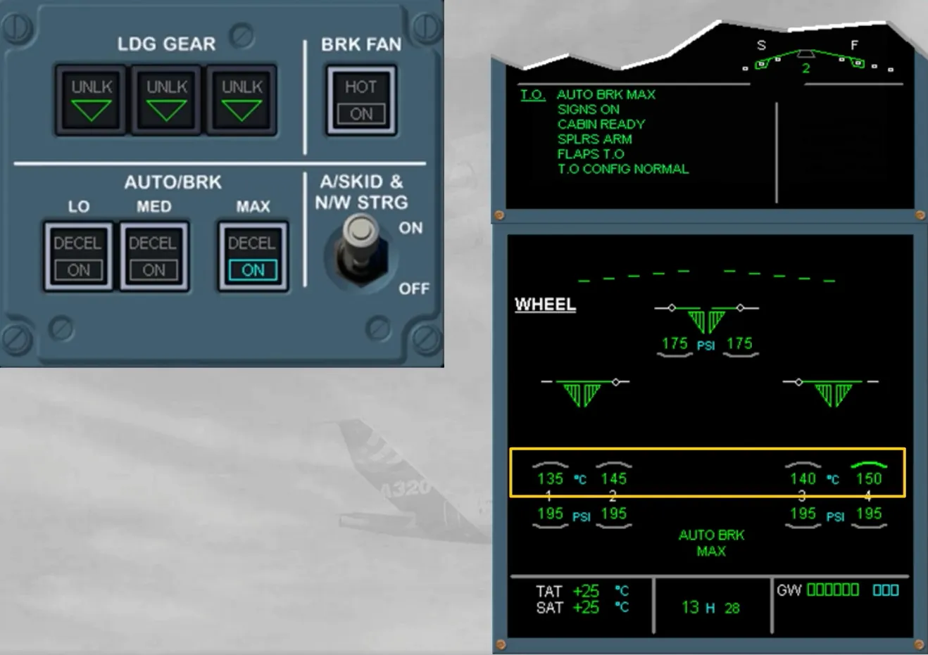
With the brake fan running, if the hottest brake temperature is above 150°C, the takeoff must be delayed, otherwise the BRK FAN pb-sw must be set to OFF.
Note: When the brake fans are running, the temperature sensors are ventilated by the blown air and they will not indicate the true brake temperatures. Expect a significant temperature increase after stopping the brake fans. Takeoff must be always delayed if the brake temperature is now above 300℃.
While taxiing the aircraft, never use simultaneously the hand wheels and the rudder pedals, as their steering orders are algebraically added.
Notice that the BSCU will limit in either direction:
- The hand wheel orders up to 75° until 20 knots and progressively to 0° reaching 80 knots
- The rudder pedal orders up to 6° until 40 knots and progressively to 0° reaching 130 knots.
So, during takeoff, the aircraft direction will be controlled exclusively using the rudder pedals.
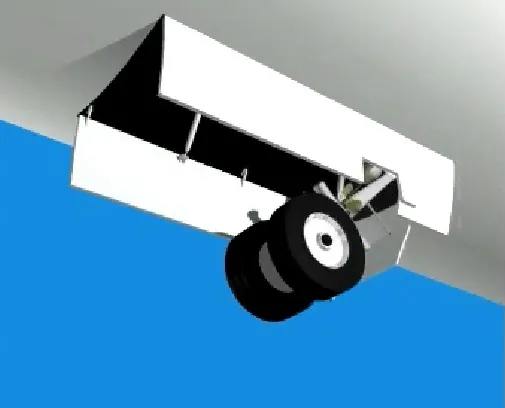
After lift-off, the landing gear lever can be set to UP, provided both main gears are not compressed and the nose wheel steering has been centered by its internal cam mechanism. Otherwise, the lever will be locked in DOWN position by an interlock mechanism.
Note: The interlock mechanism also prevents anyone from accidentally retracting the landing gear while the aircraft is on ground.
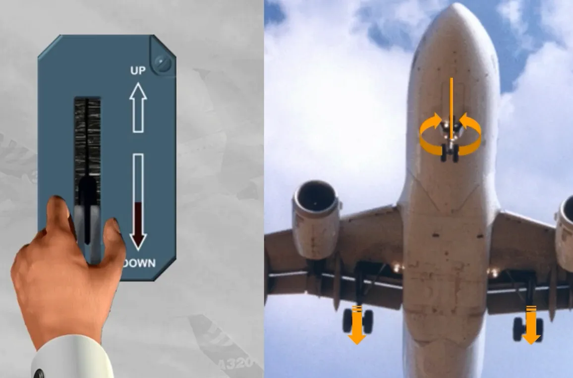
When the landing gear lever is set to UP, the landing gear retracts, as shown.
Note: While the gear doors are opening, the main wheel normal brakes are automatically applied, and the nose wheels are braked by friction bands installed in the nose gear well.

The use of the autobrake is preferable for landing.
During the descent preparation, it is recommended to use MED mode for short or contaminated runways and LO mode for long runways.
Note: For landing, it is not recommended to use MAX mode.
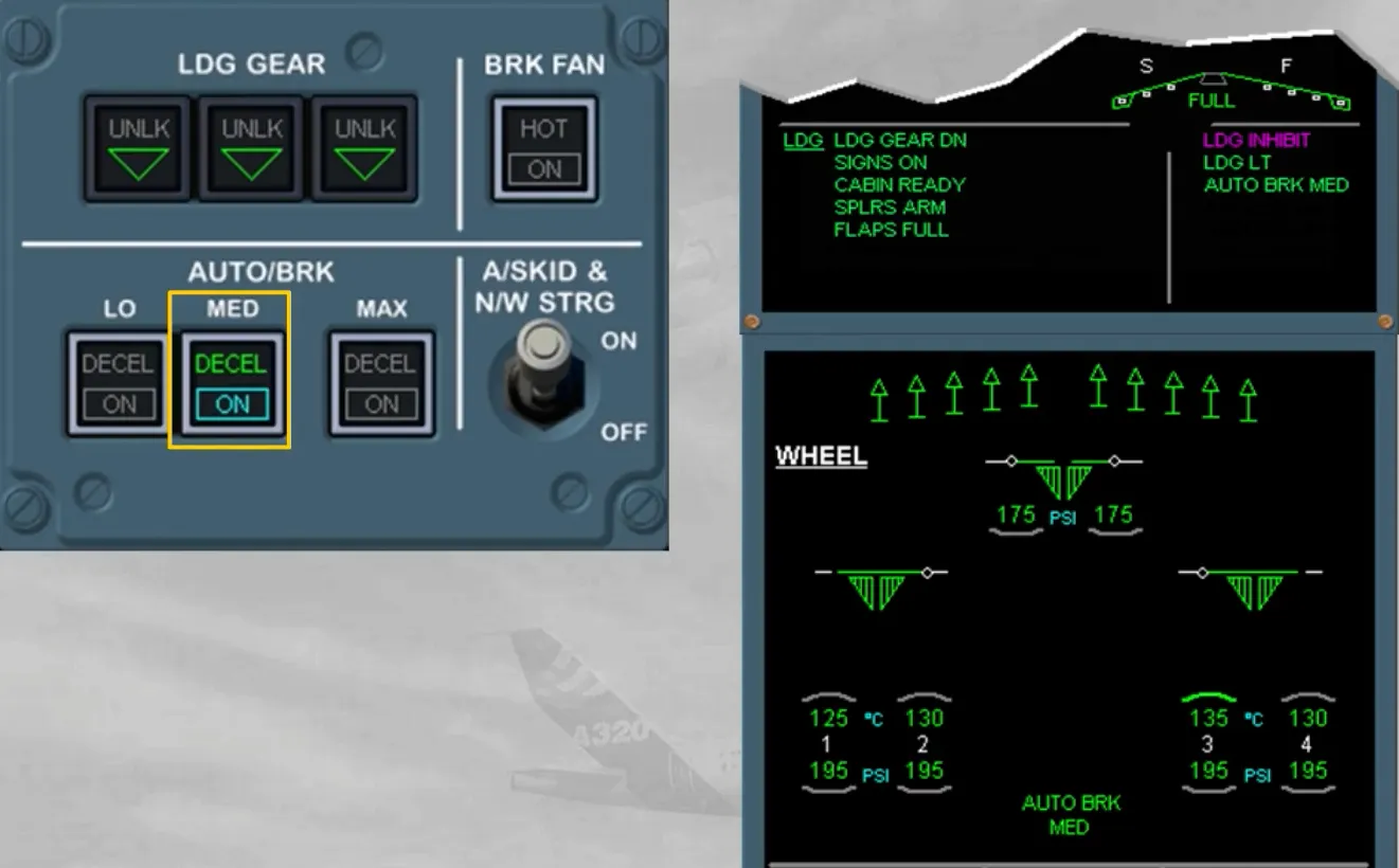
For landing today, we have armed the autobrake in MED mode, for you.
Note: If the WHEEL page is displayed it also indicates that the autobrake is armed.
It is also indicated on the right memo, but only during the LDG INHIBIT phases of the ECAM.
Also, absence of braking pressure must be checked on the ACCU PRESS & BRAKES indicator. If residual pressure is indicated you have to refer to the QRH.
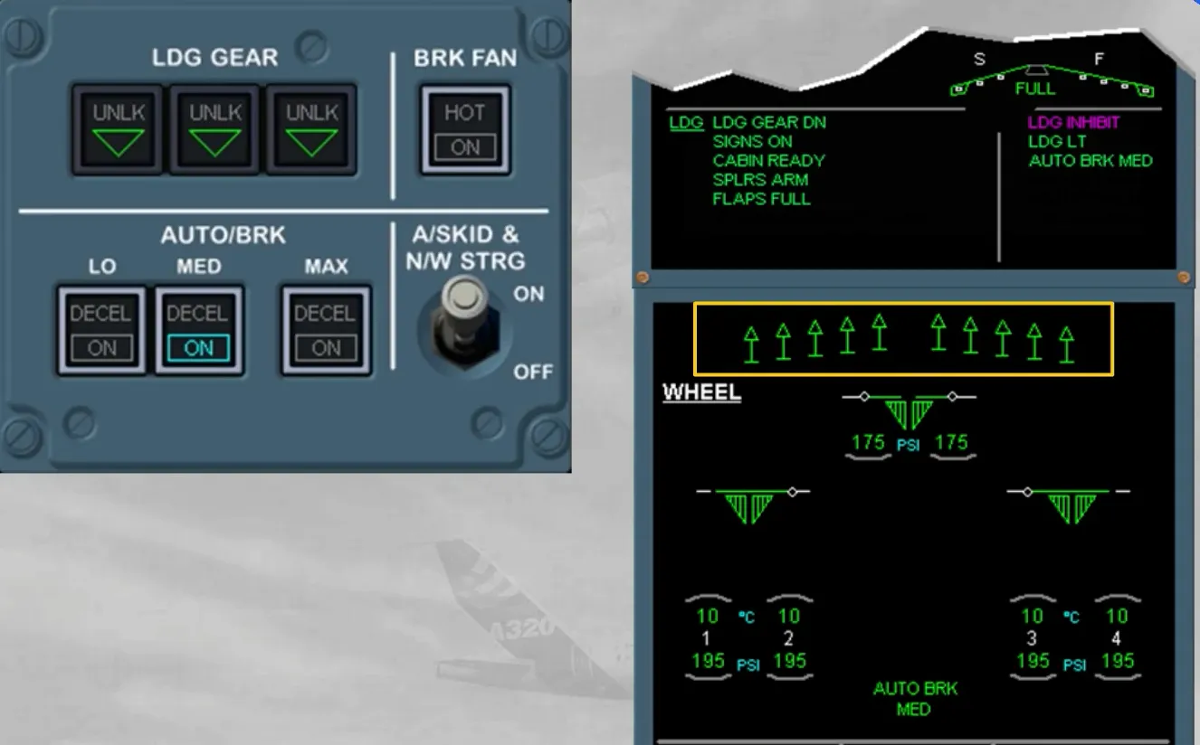
Few seconds after the ground spoilers are commanded to extend, the autobrake becomes active and sends progressive braking pressure, in order to decelerate the aircraft at selected rate. A green DECEL light comes on when the actual deceleration is 80% of the selected rate.
Note: On a slippery runway, the selected deceleration rate may not be reached due to antiskid protection. So, the aircraft will stop but without DECEL light. This does not indicate a malfunction.
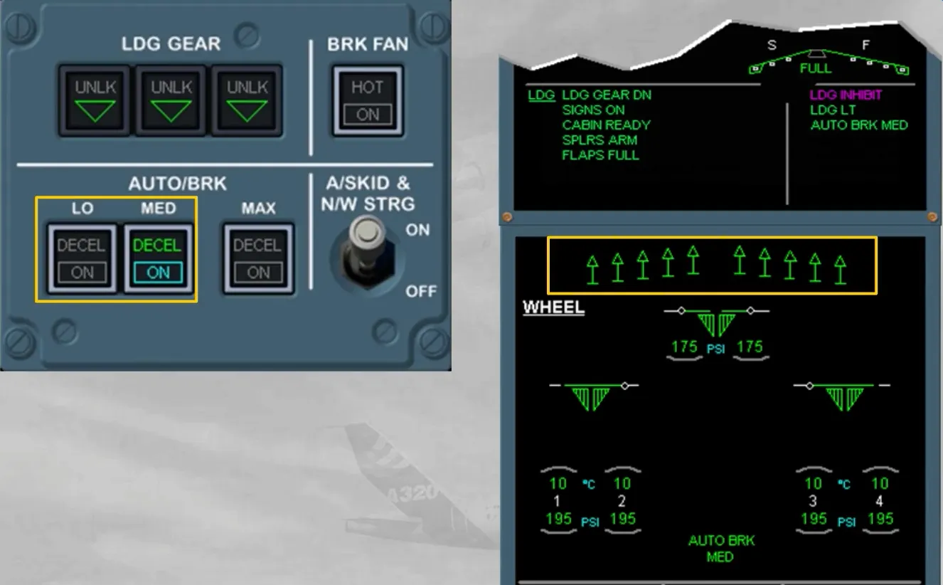
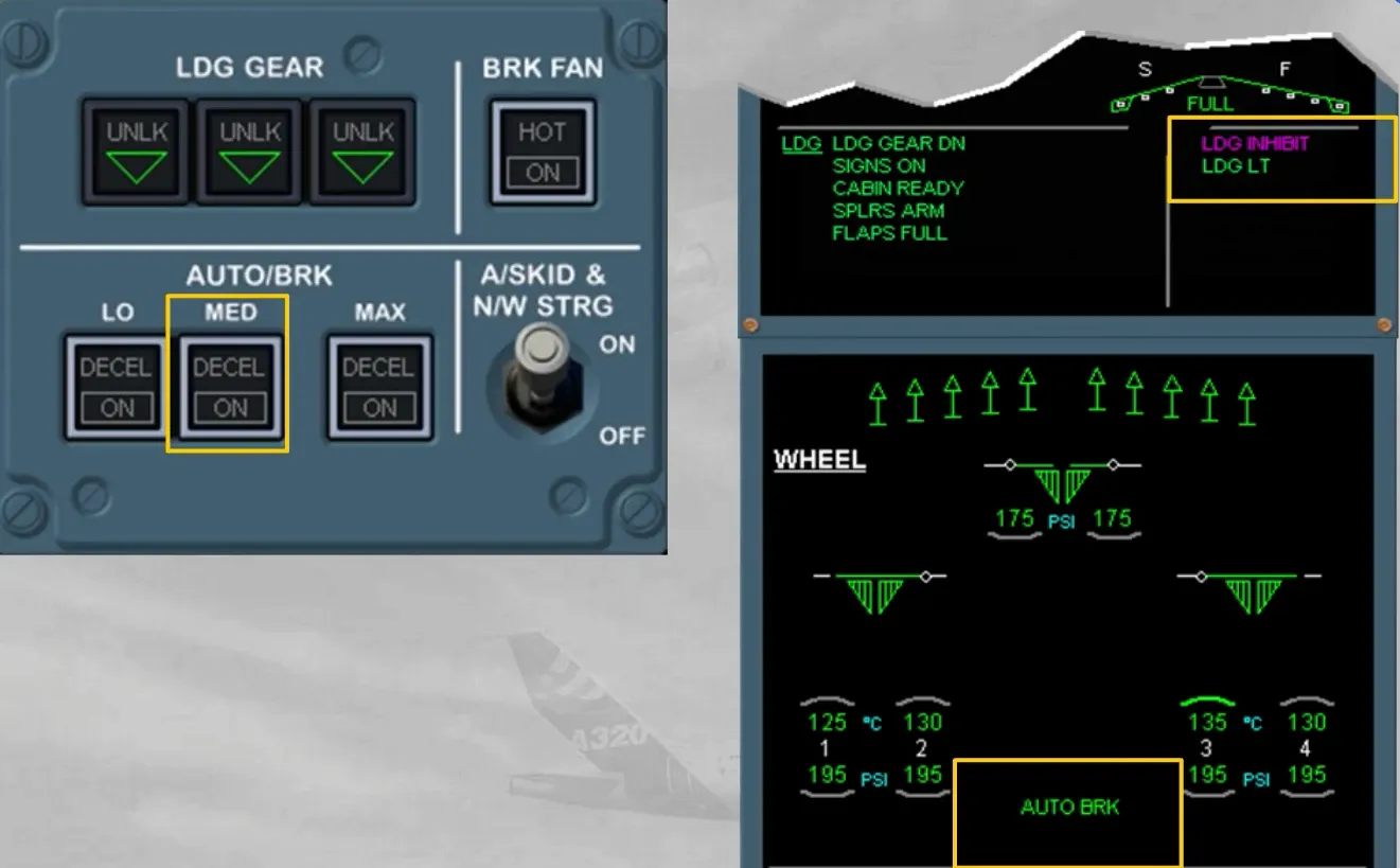
At any moment, the pilot may deactivate the autobrake:
- By applying a sufficient deflection to at least one brake pedal, or
- By deselecting the related mode. The autobrake deactivation is confirmed as shown.
Note: If the ground spoilers are retracted, the autobrake will deactivate but it will stay armed.
After landing, the brake temperature must be checked to detect discrepancies between brakes, and high temperature.
Brake fans selection should be delayed for few minutes after landing or done just before stopping the aircraft at the gate, in order to allow thermal stabilization and to avoid oxidation of brake surface hot spots.
Note: The brake fans must be used without delay, for short turnaround times or if the brake temperatures are likely to exceed the limitation (refer to your documentation).
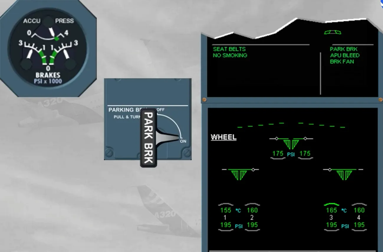
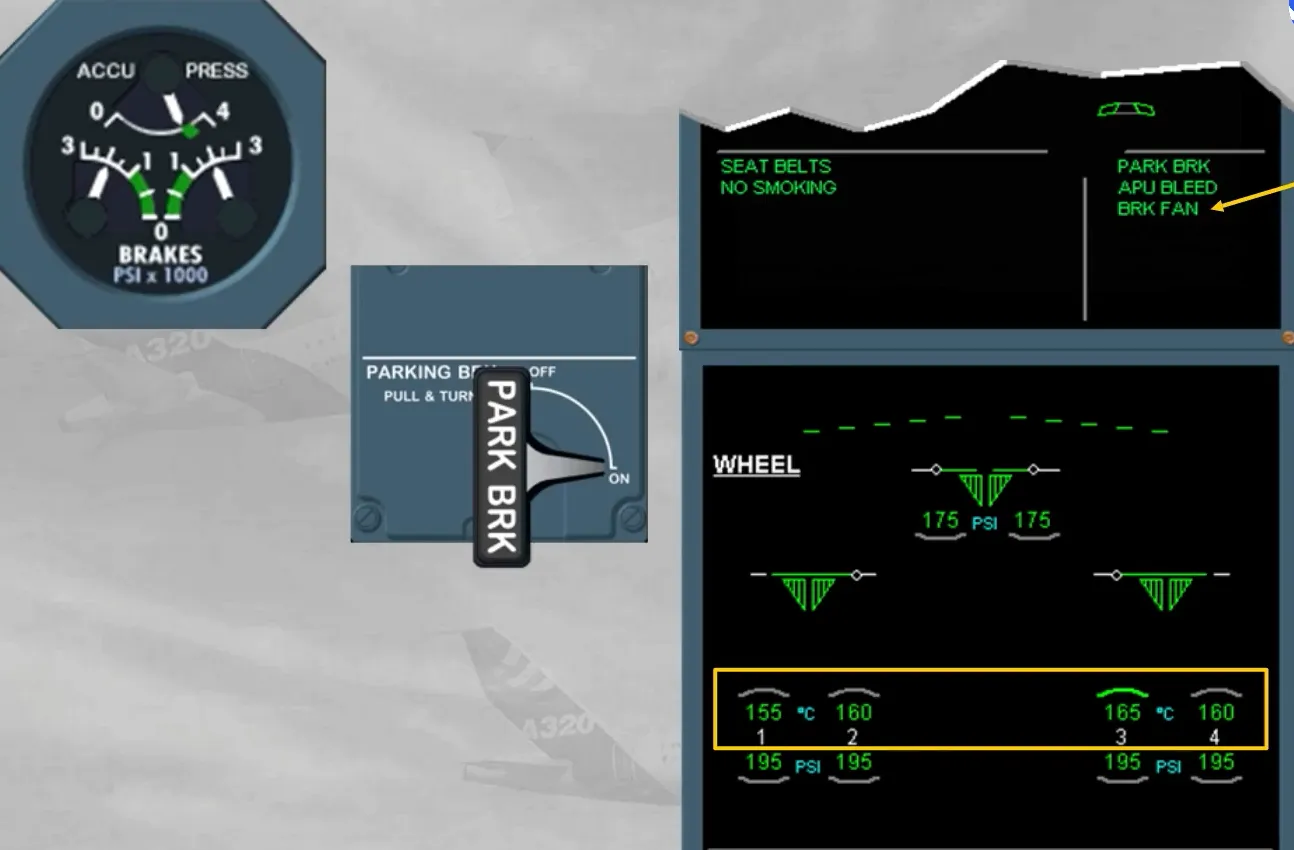
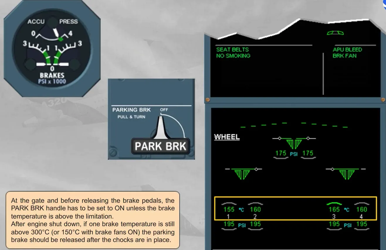
At the gate and before releasing the brake pedals, the PARK BRK handle has to be set to ON unless the brake temperature is above the limitation.
After engine shut down, if one brake temperature is still above 300℃ (or 150℃ with brake fans ON) the parking brake should be released after the chocks are in place.
Then, when the brake temperature doe not require to keep the brake fans ON, the parking brake should be kept ON in order to reduce hydraulic leak rate in the brake accumulator.
Module completed