Electrical System
The A320 electrical system is quite similar to electrical systems which you are familiar with. It is simply more automatic and easier to use.
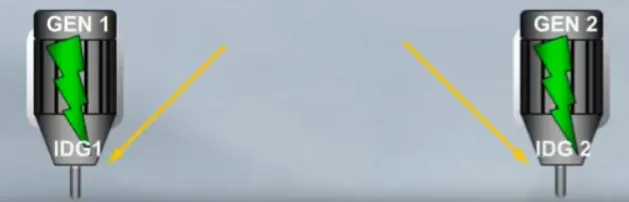
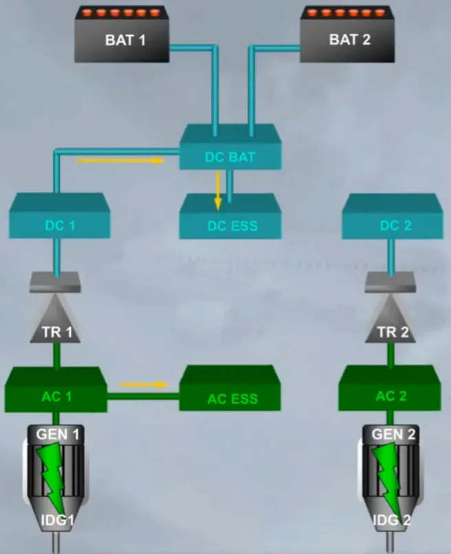
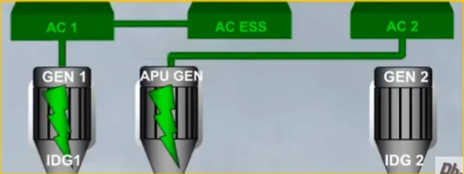
There are two engine driven generators.
The generators maintain a constant speed by a drive mechanism known as an Integrated Drive Generator (IDG).
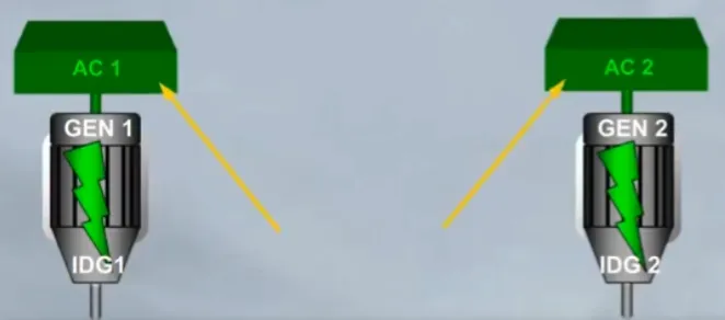
Each generator supplies Alternating Current(AC) to its own bus:
- Generator 1 to AC bus 1
- Generator 2 to AC bus 2.
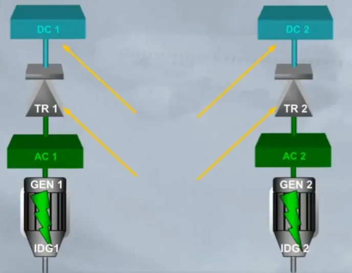
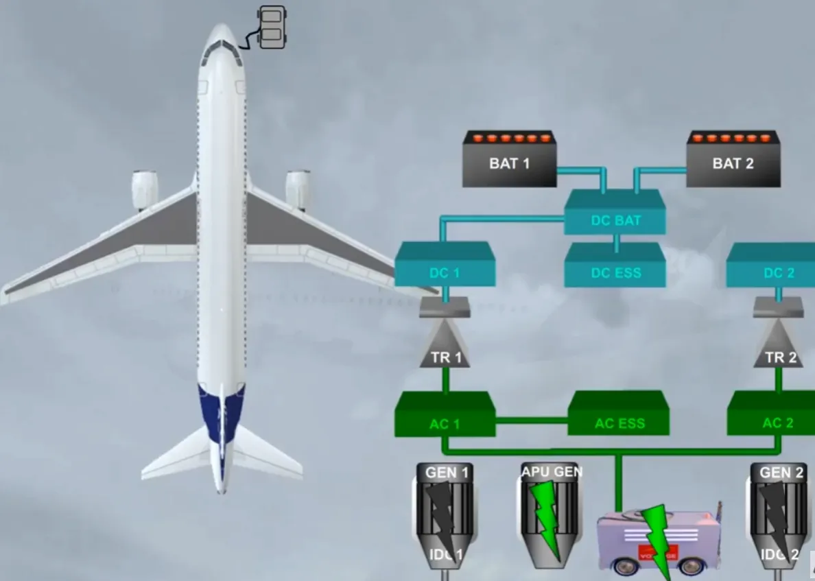
Each AC bus supplies its own Transformer Rectifier (TR):
- AC bus 1 to TR1
- AC bus 2 to TR 2.
The TRs convert alternating current (AC) into direct current (DC) to supply their related DC buses, DC 1 and DC 2.
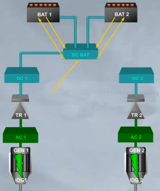
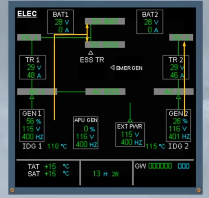
DC bus 1 feeds the DC battery bus (DC BAT).
The DC BAT bus can charge the batteries or receive power from the batteries, as required. This will be further explained in the operation module.
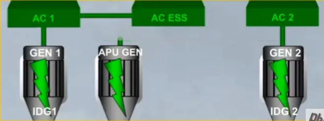
The electrical system also includes two essential buses:
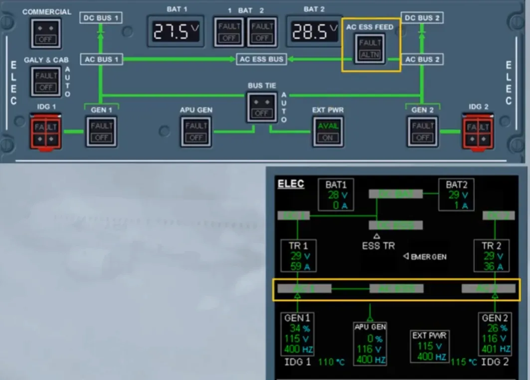
- The AC ESS bus, normally fed by AC bus 1
- Note: If the AC bus 1 is lost, the AC bus 2 automatically takes over
- The DC ESS bus, fed by DC bus 1 via DC BAT bus.
This is the basic electrical system. We will now introduce some other components which supply the basic system.
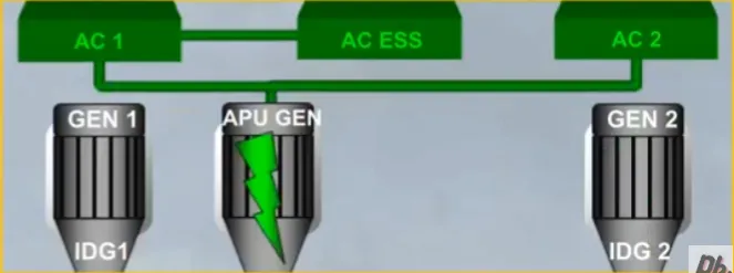
The electrical network can also be supplied by the APU generator.
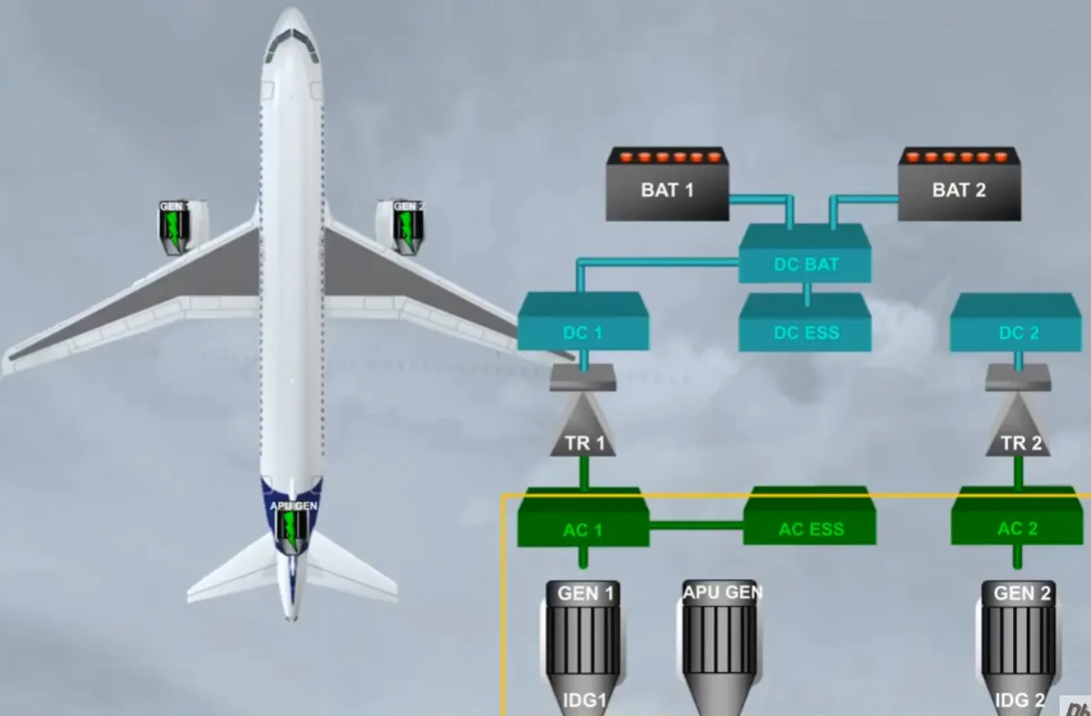
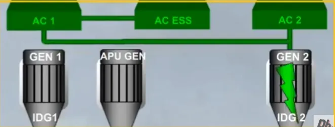
These three generators are all identical and any one of them can supply the entire aircraft electrical needs. For that a Bus Tie Contactor (BTC) logic allows the AC buses to be supplied from:
- Only one engine generator or
- Only the APU generator or
- An engine generator and the APU generator or
- Both engine generators.
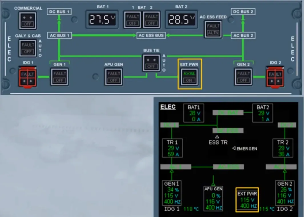
On the ground, the AC buses can be supplied by an external power source through the BTC logic.
Note: If the APU generator and the EXT PWR are connected together to the AC buses, the EXT PWR has priority over the APU generator.
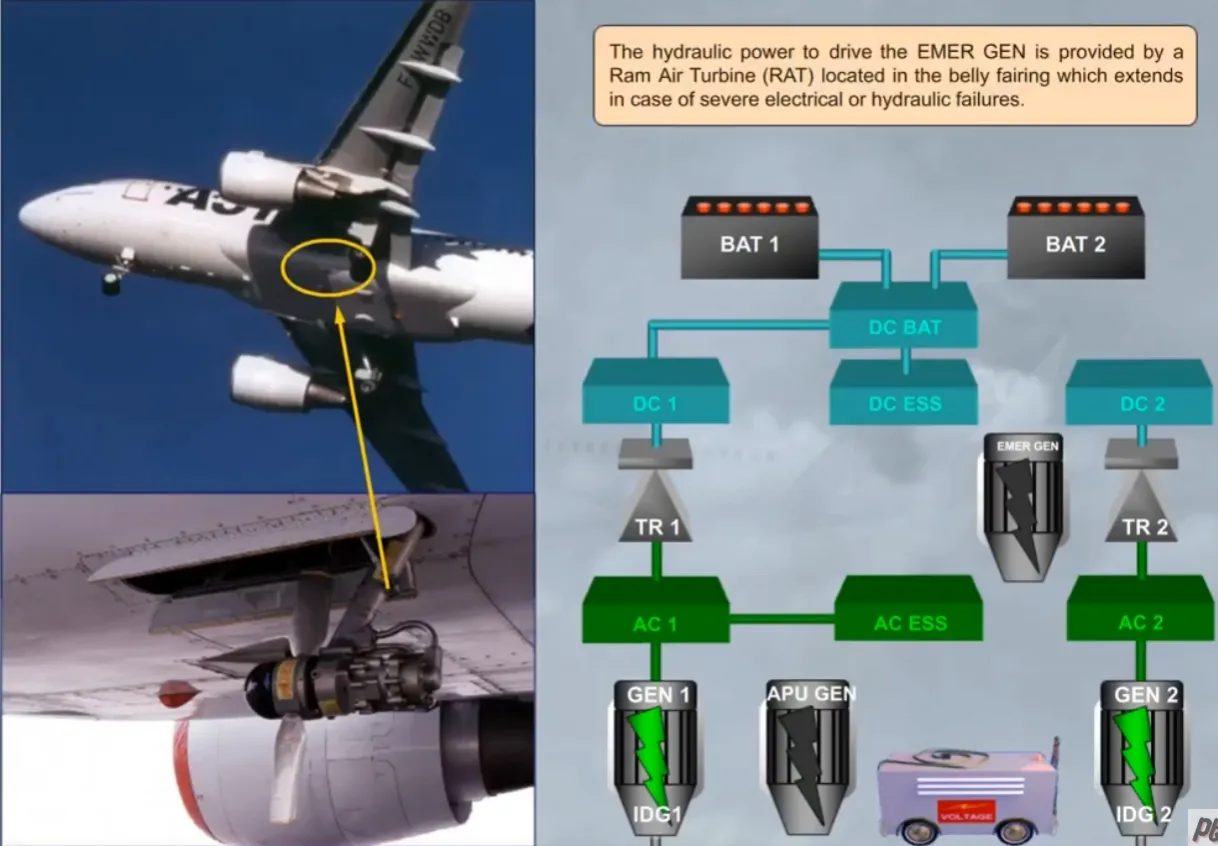
As a backup, there is a hydraulically driven emergency electrical generator (EMER GEN).
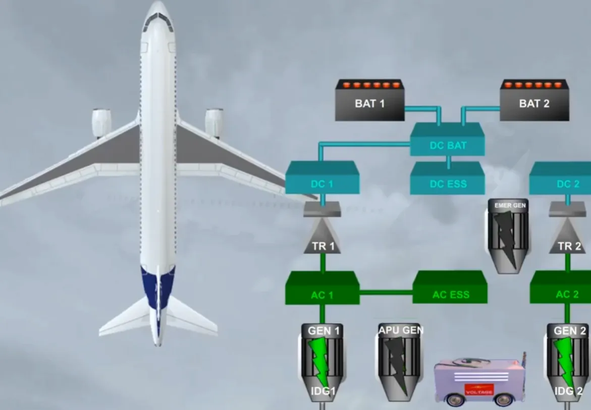
The hydraulic power to drive the EMER GEN is provided by a Ram Air Turbine (RAT) located in the belly fairing which extends in case of severe electrical or hydraulic failures.
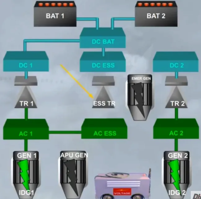
The electrical system also has an essential Transformer Rectifier (ESS TR).
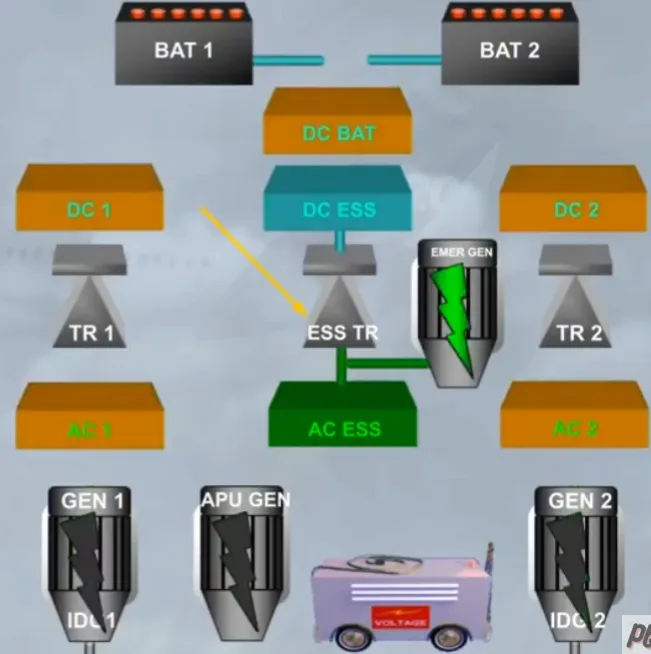
The ESS TR can power the DC ESS bus:
- From the EMER GEN in case of severe electrical failure or
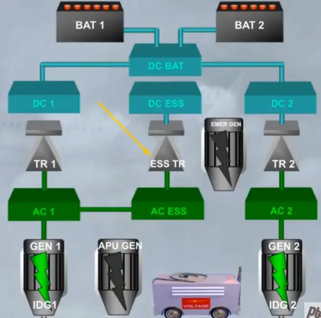
- From the AC ESS bus in case of a TR 1 or a TR 2 failure.
Note: In this case the DC bus 1 (or 2) is transferred to the DC bus 2 (or 1) via the DC BAT bus.
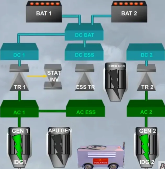
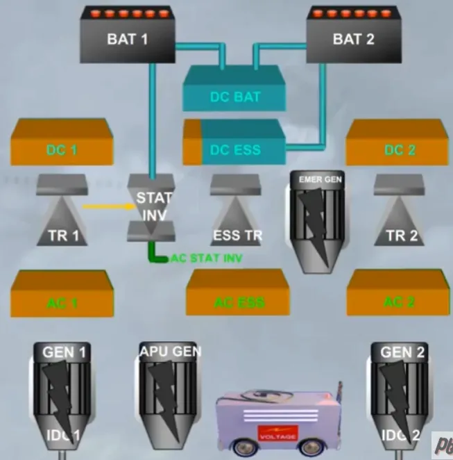
Finally, a static inverter allows part of the AC electrical network to be supplied from the BAT 1, when only batteries are connected:
- On ground, it supplies an AC STAT INV bus and the BAT 2 will supply partially the DC ESS bus
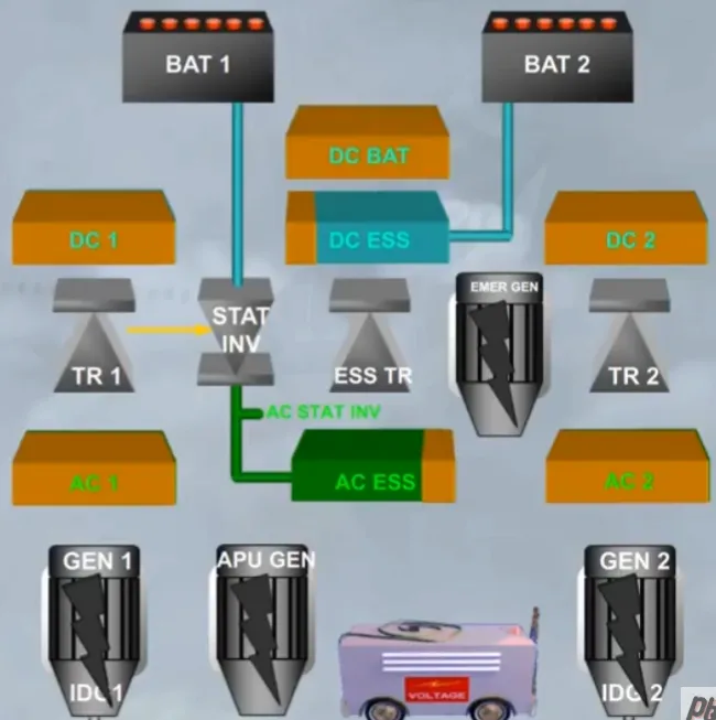
- In flight, it supplies also partially the AC ESS bus and the BAT 2 partially the DC ESS bus. But the DC BAT bus is not supplied.
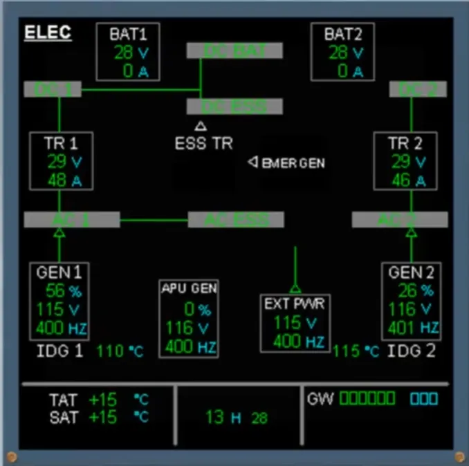
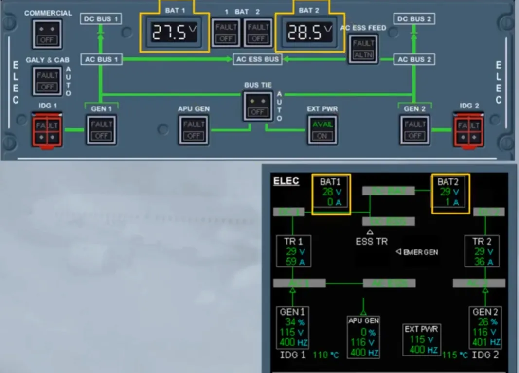
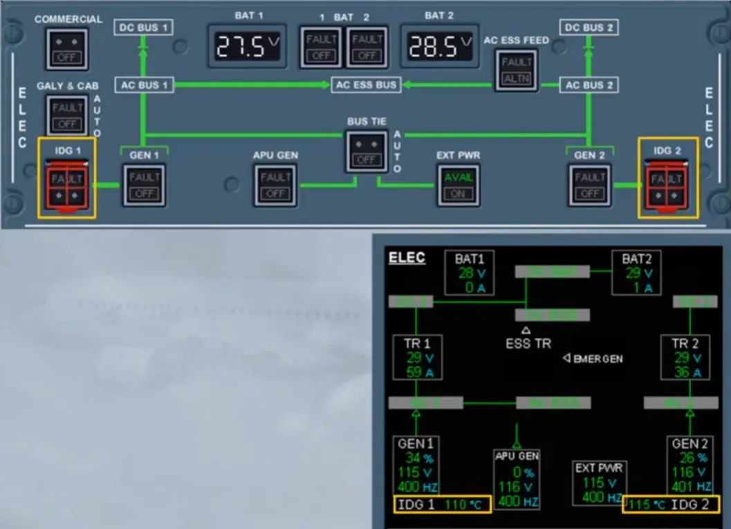
Now, let’s see how this information is presented to the pilots in the cockpit. We will introduce the ECAM ELEC page.
You can see that most of the components we have talked about are displayed on the ECAM page.
Note: The static inverter indication will replace the EXT PWR indication only during its test and provided the essential buses are supplied by the batteries.
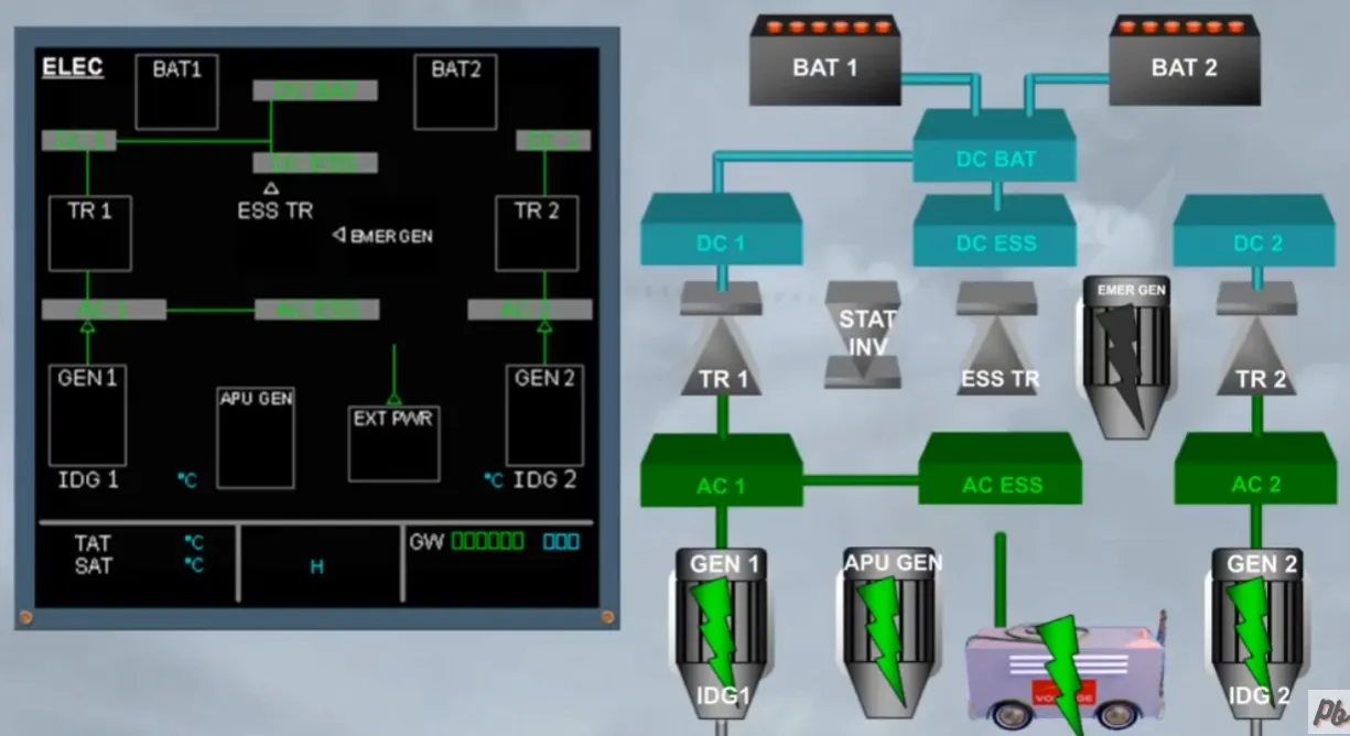
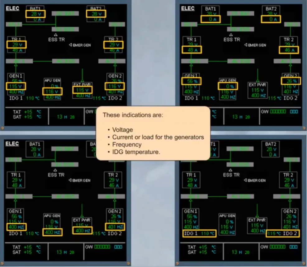
As shown, each component can be monitored via its indications.
These indications are:
- Voltage
- Current or load for the generators
- Frequency
- IDG temperature.
You can also notice the different connections displayed via green lines.
Let’s now locate pilots controls.
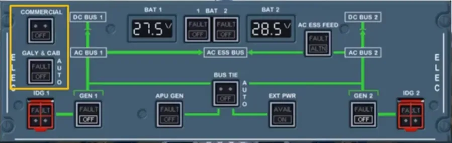
The ELEC panel is located on the overhead panel.
Note: The controls, installed on the left hand side, will depend on the options. So, refer to your documentation.
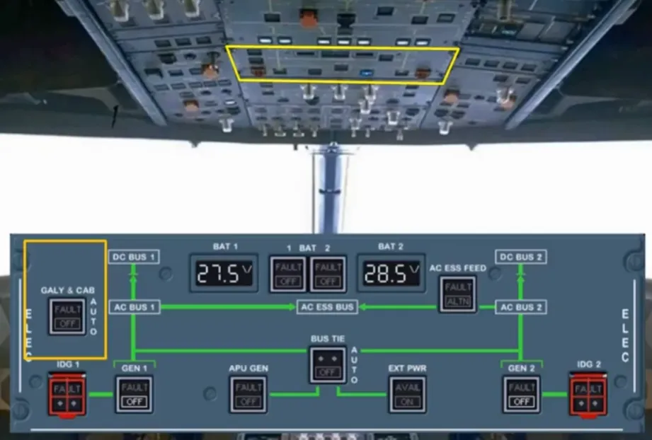
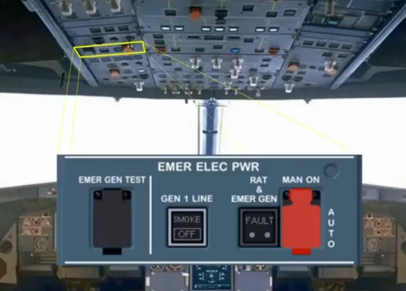
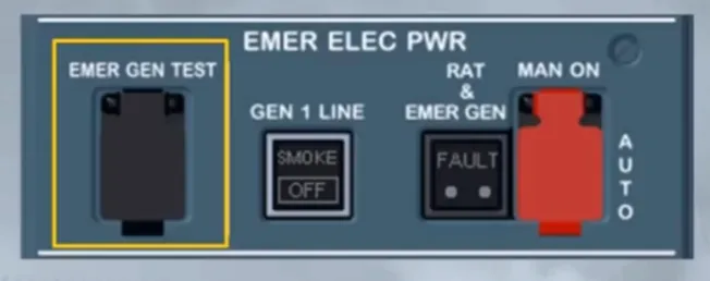
For emergency cases, there is an EMER ELEC PWR panel on the left side of the overhead panel. Now let’s look at the relationship between the ELEC panel and the ECAM ELEC page.
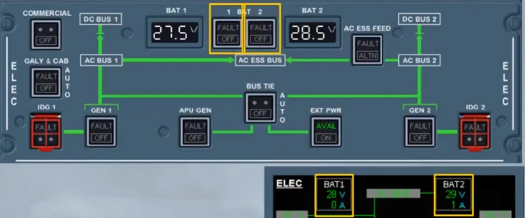
The battery voltage can be monitored either on the overhead panel or on the ECAM page.
Each battery is controlled by a pb-sw.
Both main generators and the APU generator are controlled by their associated pb-sw.
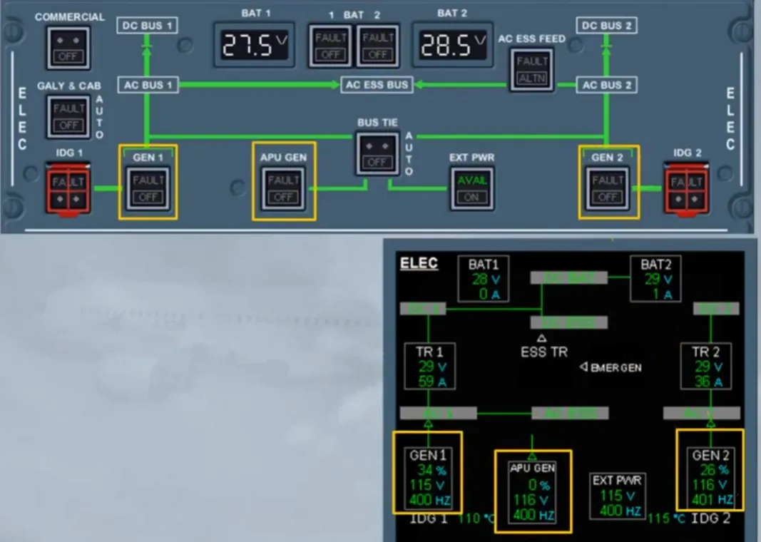
The external power is also controlled by a pb.
The AC ESS FEED pb-sw enables thepilots to change the supply to the ACESS bus from AC bus 1 to AC bus 2.
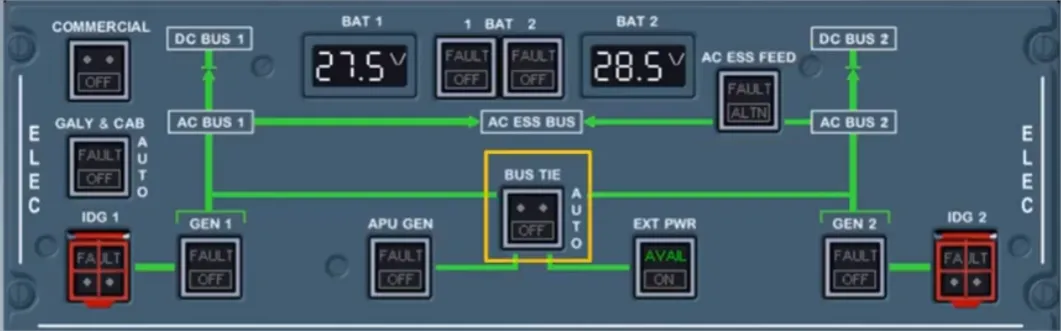
The BUS TIE pb-sw enables the pilots to isolate one side of the system from the other.
In case of failure, these pushbuttons enable you to disconnect an IDG from its drive shaft.
The controls and indications on the EMER ELEC PWR panel will be covered in the FAILURE CASES module.
Except for the EMER GEN TEST switch. It is used by maintenance only to test the emergency generator and the static inverter.
Module completed
Video study
Section titled “Video study”- Watch the video available on YouTube