Flight Controls Failure Cases
Let’s first see the redundancy aspects of the flight controls.
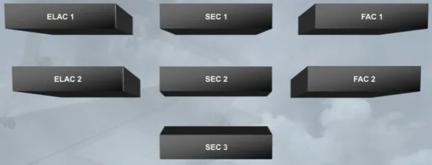
The ELACs are used for the normal control of elevators, THS and ailerons, the SECs are used for the normal control of spoilers and the FACs are used for the control of the rudder, rudder trim and yaw damper.
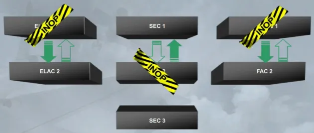
In case of a computer failure, the second computer of the same type takes over.
Note: The SEC 3 is only used for spoiler control.
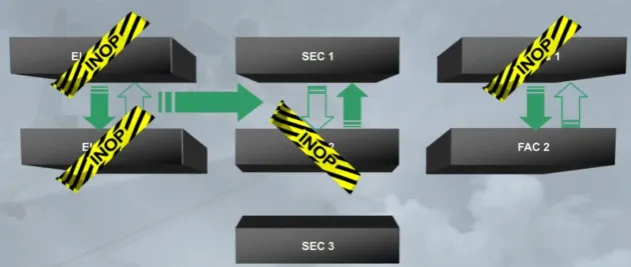
In case of both ELACs failure, the SEC 1 and 2 participate to the flight control system reconfiguration for the control of the elevators and THS.
Each flight control surface is supplied with different hydraulic sources:
- 2 for ailerons, elevators and THS
- 3 for the rudder and spoilers.
Note: Each spoiler is supplied by only one of the 3 hydraulic sources.
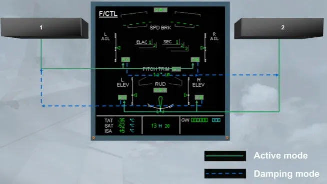
Each hydraulic source operates independently the related flight control surface by means of an actuator.
Each hydraulic actuator is electrically controlled by a flight control computer in two modes:
- Active mode, or
- Damping mode.
When a surface has two actuators:
- One is in active mode, controlled by its related computer and
- The other is in damping mode and follows the surface movement, monitored by its related computer.
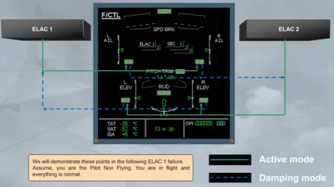
We will demonstrate these points in the following ELAC 1 failure. Assume, you are the Pilot Non Flying. You are in flight and everything is normal.
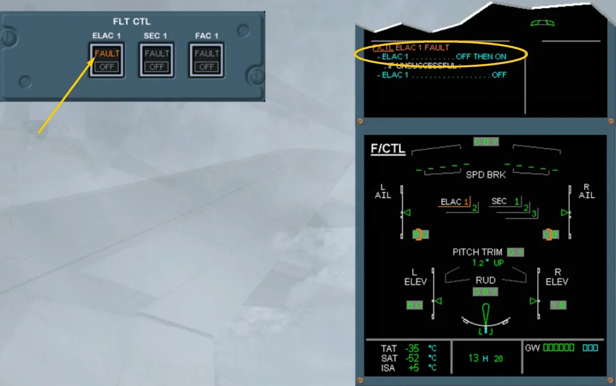
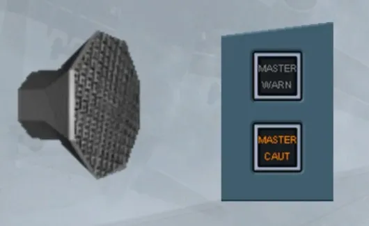
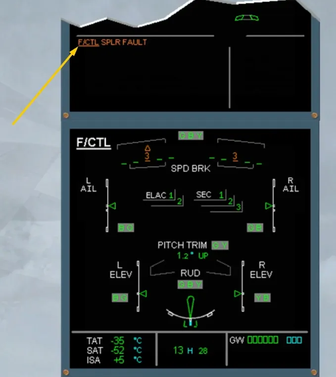
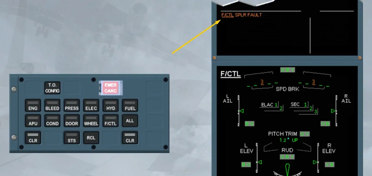
On the E/WD, read the title of the failure.
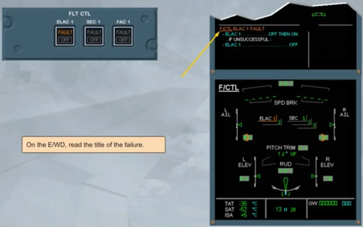
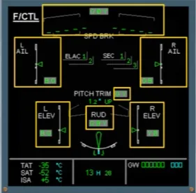
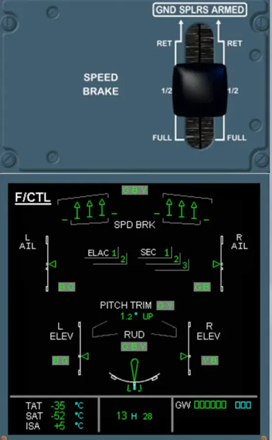
On the ECAM F/CTL page, observe:
- The related failed computer is shown in amber
- The related lost actuator control is shown partially boxed amber. This indicates that the actuator control has automatically reverted to damping mode and
- The related other actuator is still in green. This confirms that the related actuator control has automatically reverted to active mode and is controlled by its related flight control computer.
Also, on the FLT CTL panel, an amber FAULT light is on, helping you to locate the pb-sw relative to the ECAM procedure.
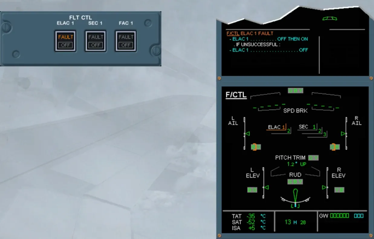
But according to the computer reset procedure, described in the QRH or FCOM, a computer can be reset by its pb-sw or by its circuit breaker (C/B).
Note: Usually, wait 3 seconds, if a pb-sw is used or refer to your documentation if a C/B is used, as it will depend on the computer.
So, we will do the ECAM actions for you.
Then, it has been set back to ON for you. Notice that for a correct reset, it is recommended to wait for an additional 3 seconds. But the reset is not successful, and we have set the ELAC 1 pb-sw to OFF. Now, the ECAM can be cleared.
So, we will do it for you.

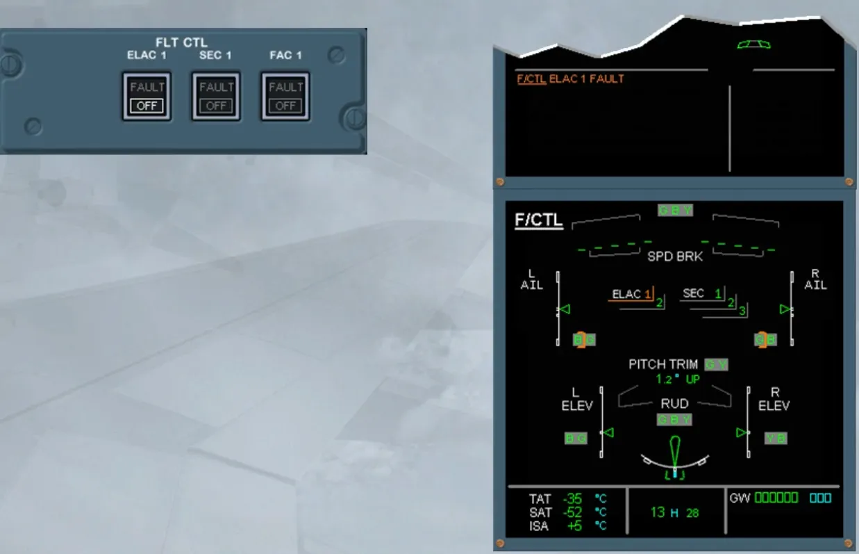
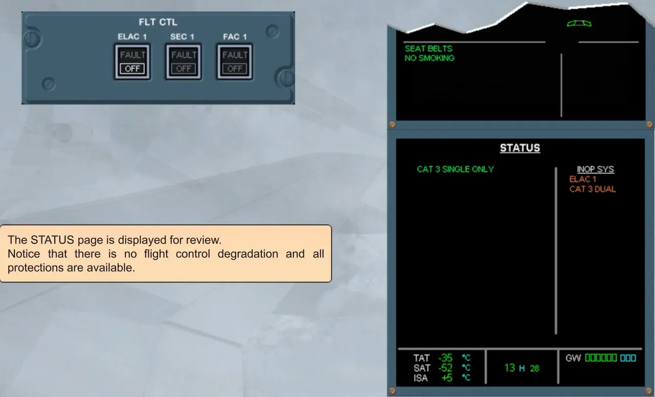
The STATUS page is displayed for review.
Notice that there is no flight control degradation and all protections are available.
We will now review the other redundancy features and protections, when the second ELAC also fails.
On the E/WD, read the title of the failure.
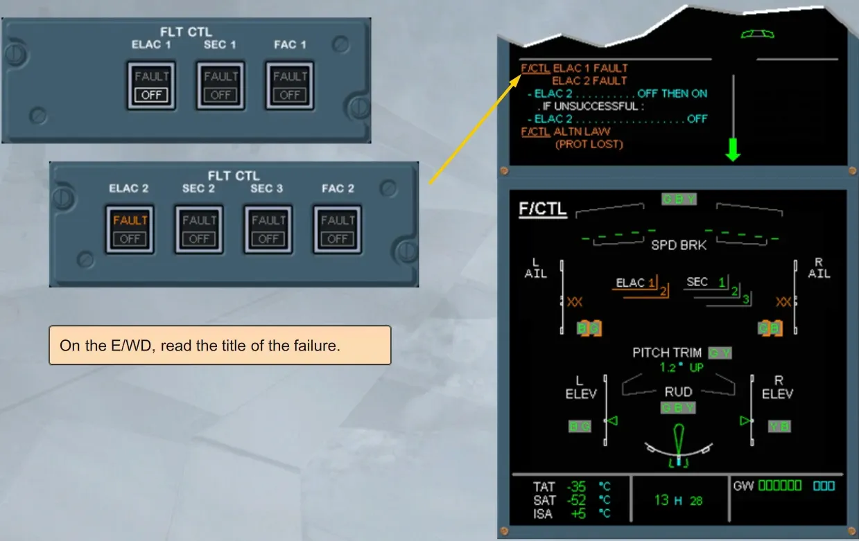
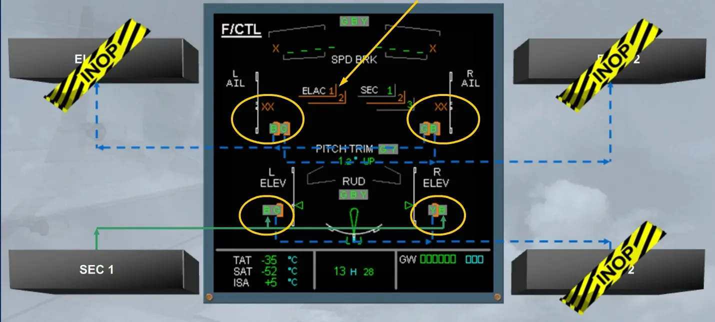
On the ECAM F/CTL page, observe:
- The related failed computers are shown in amber
- Both aileron actuators are shown partially boxed amber. This indicates that the actuator controls have automatically reverted to damping mode. Also aileron position indications are replaced by amber crosses
- Both actuators of the elevators are still in green. This confirms that their controls have been automatically transferred to the SECs. The elevator actuators controlled by the SEC 2 are in active mode and those controlled by the SEC 1 are in damping mode.
Note: The control of the THS has been also transferred to the SEC 2 and the roll control is ensured by only the spoilers which are controlled by their related SEC.
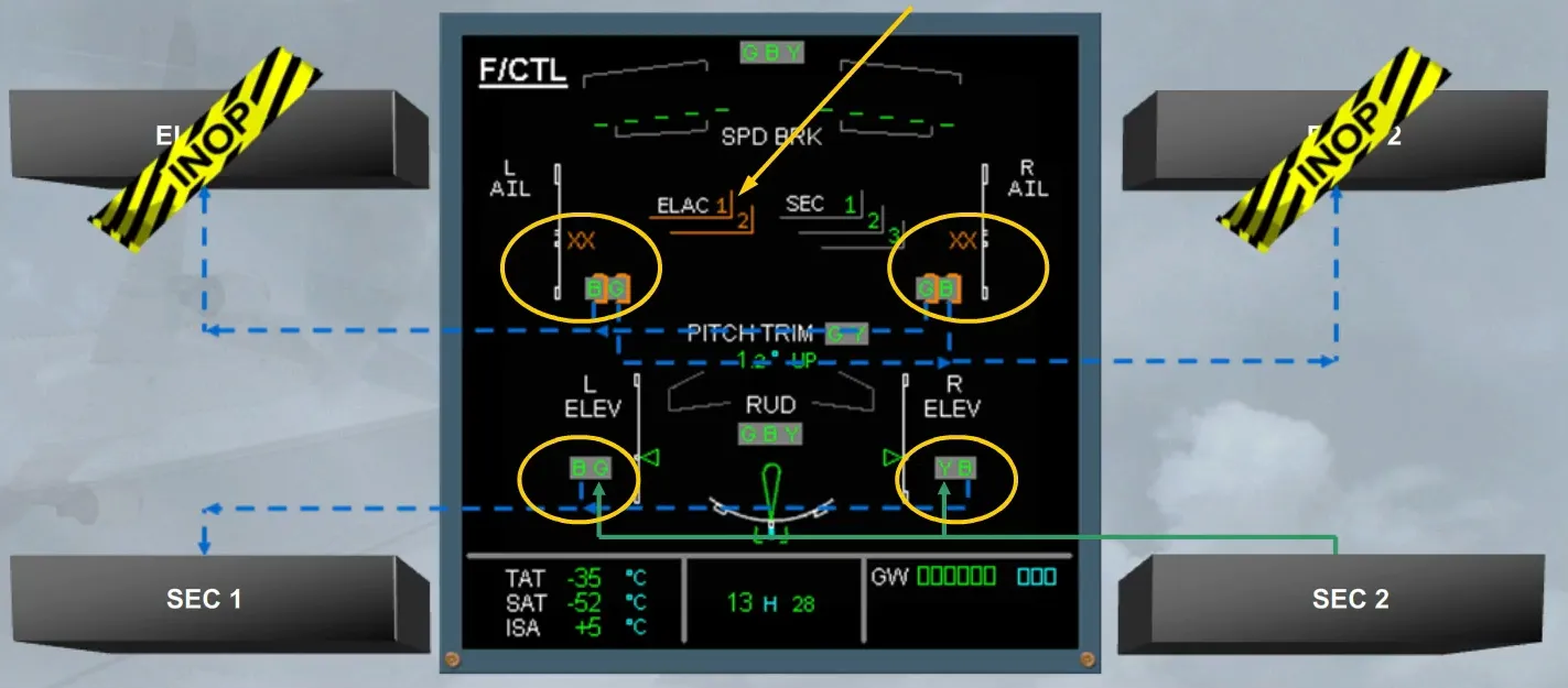
In the very low probability of SEC 2 failure, it will be replaced by SEC 1 which will control the related elevator actuators and also the THS.
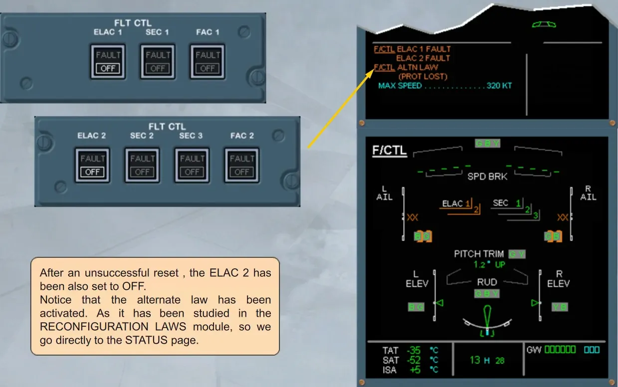
After an unsuccessful reset , the ELAC 2 has been also set to OFF.
Notice that the alternate law has been activated. As it has been studied in the RECONFIGURATION LAWS module, so we go directly to the STATUS page.
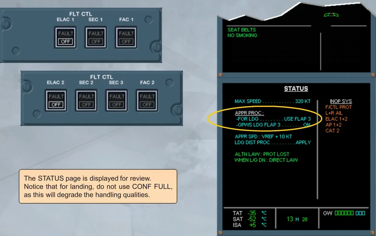
The STATUS page is displayed for review.
Notice that for landing, do not use CONF FULL, as this will degrade the handling qualities.
Another case of failure is an elevator fault.
In this case, the deflection of the remaining one is limited to avoid excessive asymmetrical loads on the tail or rear fuselage and to reduce the asymmetry effects.
The remaining surface is sufficient to resume normal flight.

In case of total loss of electrical control of the elevators, their actuators are automatically set to centering mode and maintain hydraulically the neutral position.
If the total loss of the elevators is due to hydraulic failures, their actuators will be automatically set to damping mode.

The THS is moved by two hydraulic motors. These hydraulic motors are controlled:
- By one of the three electric motors which are dedicated to ELAC or SEC, depending on computer reconfiguration
- By trim wheel mechanical linkages.
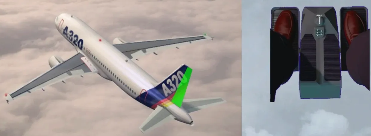
The rudder is actuated by three independent hydraulic jacks, which in turn are controlled:
- By one of the two hydraulic actuators, which are operated by the dedicated FAC, for automatic yaw damping and turn coordination
- By rudder pedal mechanical linkages.
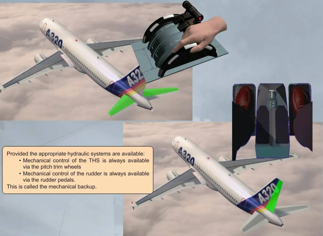
Provided the appropriate hydraulic systems are available:
- Mechanical control of the THS is always available via the pitch trim wheels
- Mechanical control of the rudder is always available via the rudder pedals.
This is called the mechanical backup.
SUMMARY
-
General rules:
- If a computer fails, the second computer of the same type takes over
- Each primary flight control surface is supplied by at least 2 different hydraulic sources. An independent actuator is associated with each hydraulic source for each surface
- Each actuator is controlled by a different computer. For a surface, one actuator is always in active mode while the other(s) are in damping mode.
-
Ailerons/elevators/THS/rudder:
- If both ELACs fail, SEC 2 controls the elevators and the THS. The ailerons are in damping mode. If SEC 2 fails, it will be replaced by SEC 1
- In case of an elevator failure, the deflection of the remaining one is limited to avoid excessive loads on the tail and rear fuselage
- Mechanical backup is always available using the rudder pedals and pitch trim wheels, provided the appropriate hydraulic systems are available.
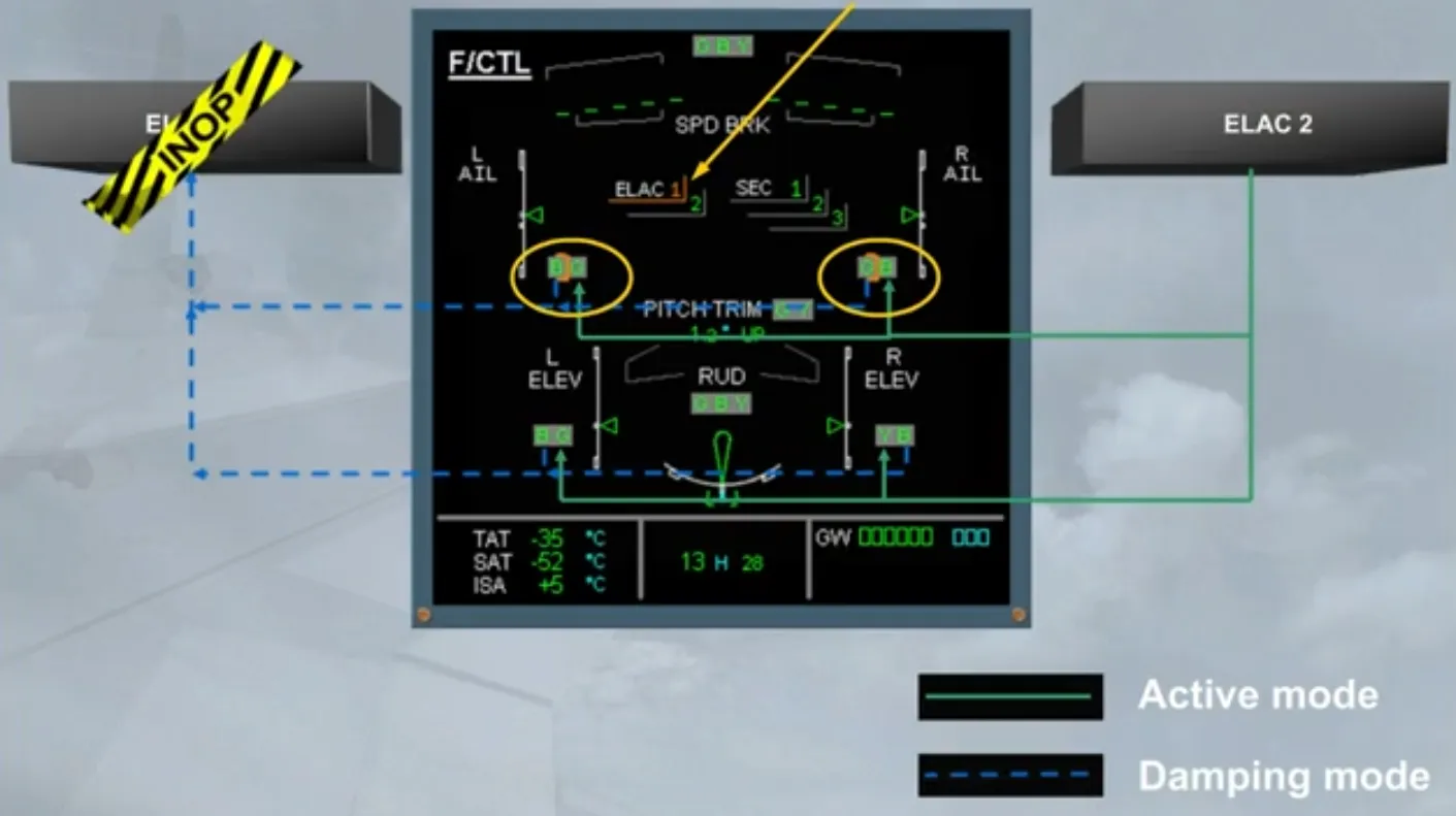
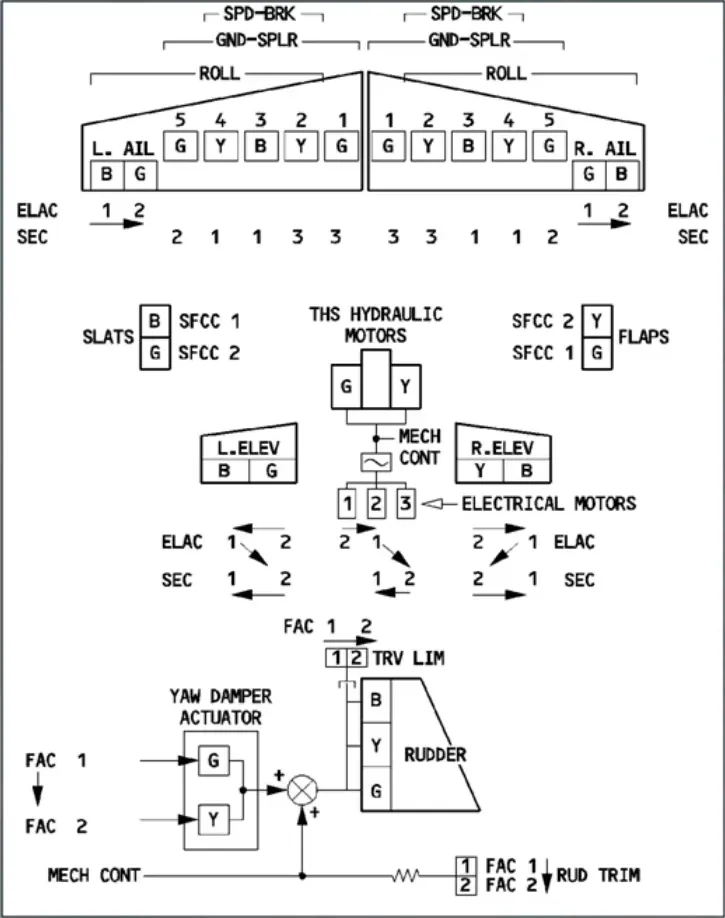
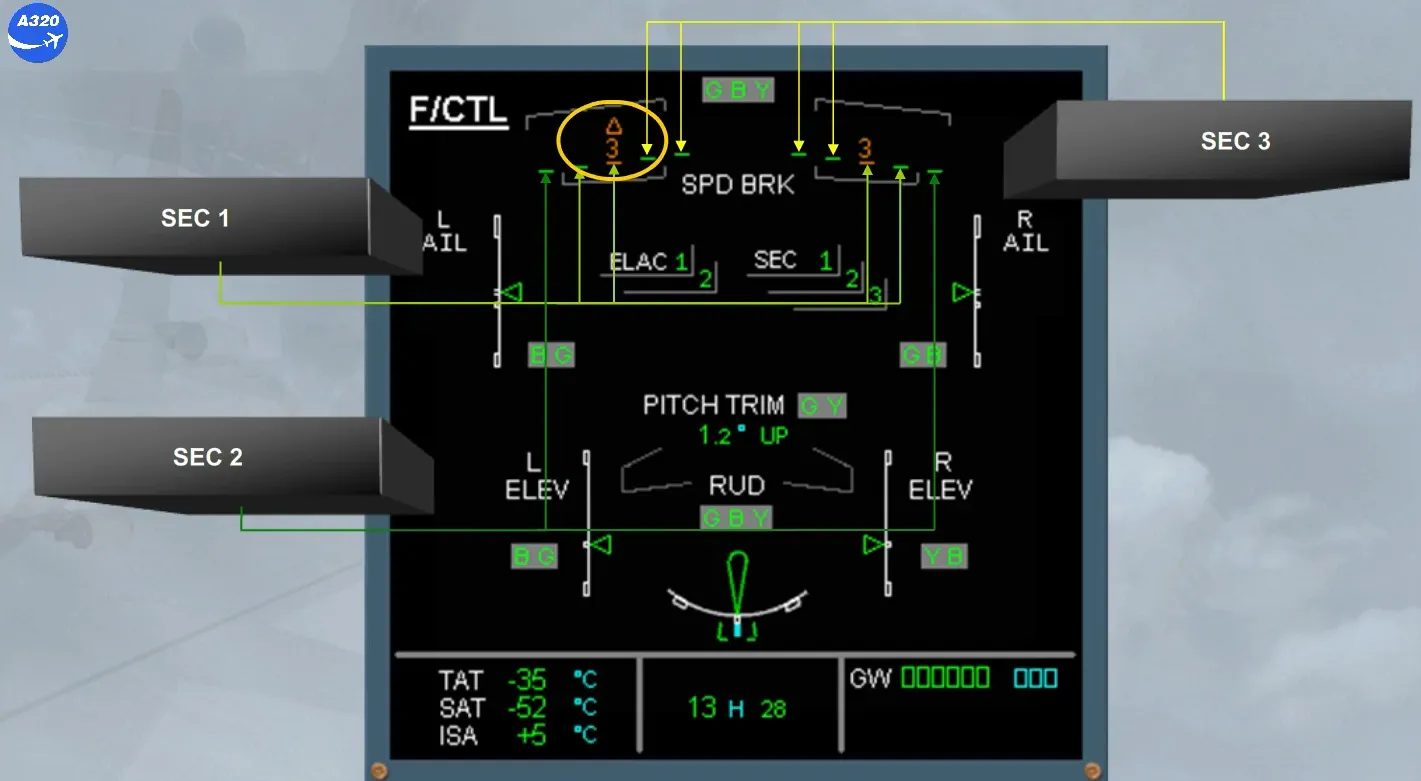
Here is a summarizing schematic.
The arrows indicate the control of reconfiguration priorities.
G B Y indicates the hydraulic power source (green, blue or yellow) for each servo control or actuator.
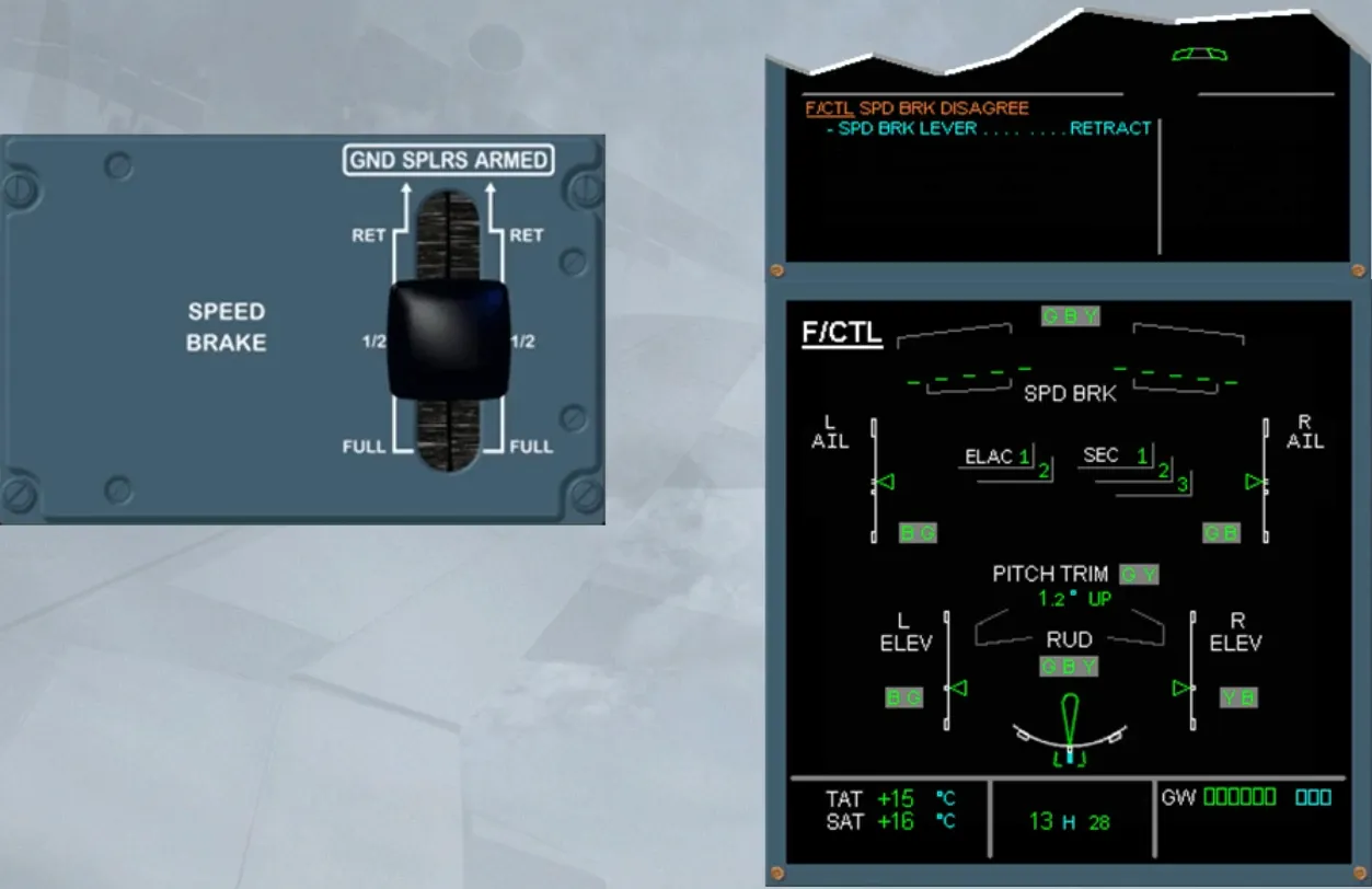
We will now see a spoiler fault.
Assume, we are in descent with speedbrakes extended and no previous fault has occurred.
We will retract the speedbrakes for you, as they are no more required.
On the E/WD, read the title of the failure.
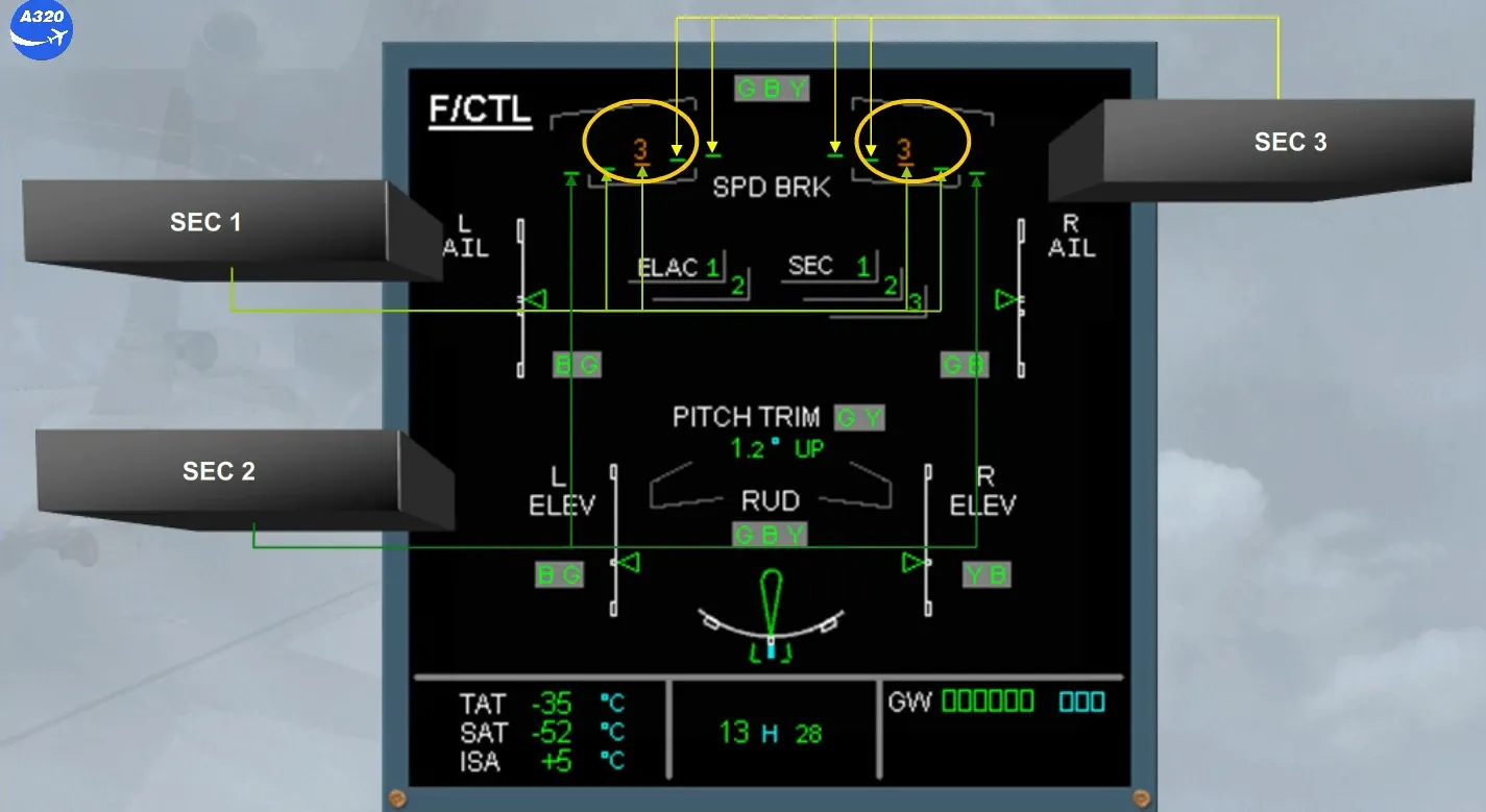
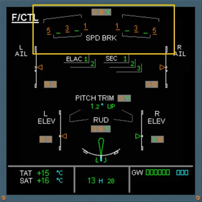
On the ECAM F/CTL page, as the spoiler control is shared by the 3 SECs, observe:
The failed spoiler, used for speedbrake function, is shown in amber, and momentarily in the extended position. This is detected by the related SEC, which has immediately controlled the actuator of the faulty spoiler to the zero position and has inhibited the symmetric one, as shown.
As no action is required in the procedure, after review and confirmation from the Pilot Flying, we will clear the ECAM for you.
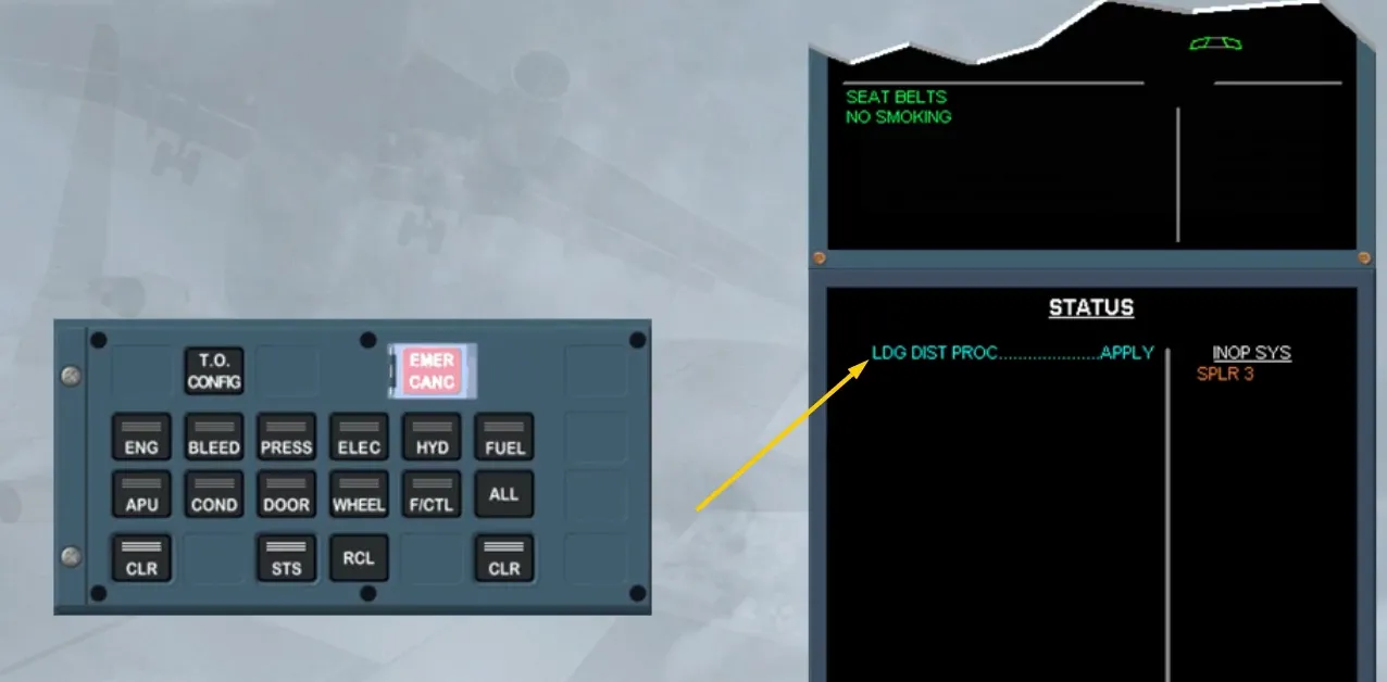
The STATUS page is displayed for review.
A blue message advises us that we will have to calculate a new landing distance.
This is due to the fact that both spoilers 3 will stay retracted when the remaining ground spoilers extend at touch down.
You can see, in the INOP SYS column, that SPLR 3 are now inoperative.
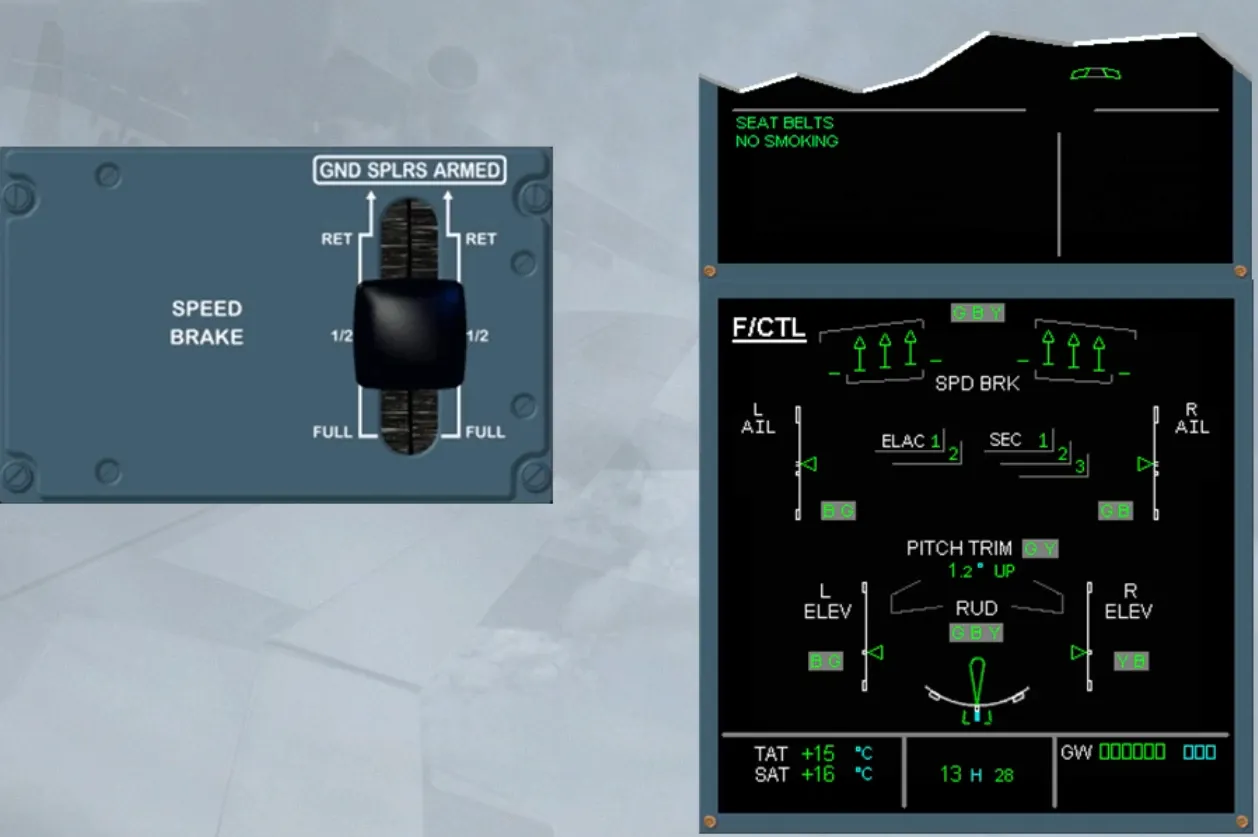
We will now review the other spoiler aspects we did not have the opportunity to see when performing the previous procedure.
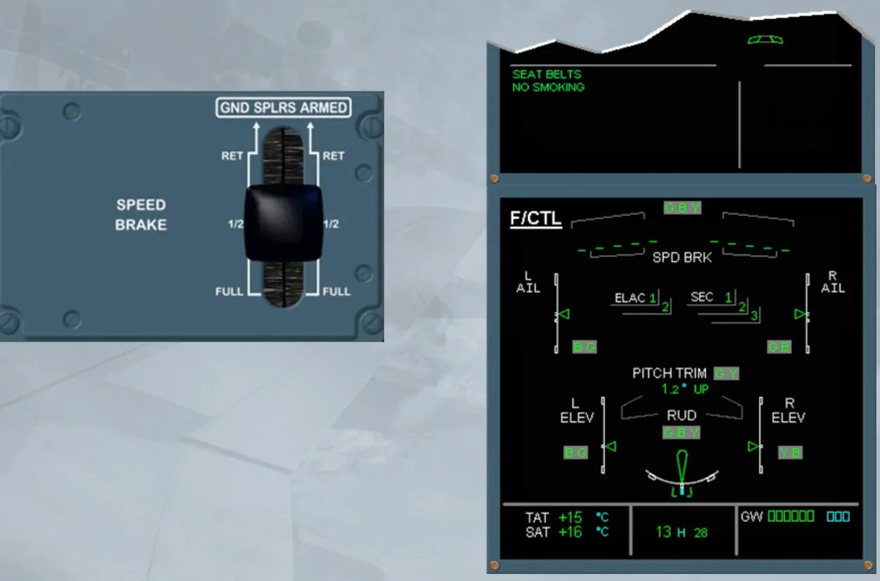
According to the failure, configuration or activated protection, the speedbrake extension may be inhibited. If the inhibition occurs when the speedbrakes are extended, they retract automatically and stay retracted until the inhibition conditions are left and the lever has been set to RET for 10 seconds or more.
Note: ECAM cautions are also triggered.
As each spoiler has a single hydraulic actuator, when this hydraulic supply is lost the related affected spoiler remains at its current deflection, unless pushed down by aerodynamic forces.
SUMMARY:
- Spoiler control is shared by the 3 SEC computers
- When a spoiler has failed on one wing, the symmetrical one is automatically inhibited
- As a general rule, spoilers are automatically retracted when faulty, inhibited or not electrically controlled
- Each spoiler is fitted with a single actuator supplied by a hydraulic source
- In case of loss of hydraulic supply, an affected spoiler remains at its current deflection unless pushed down by aerodynamic forces.
Let’s now review some slats/flaps failure cases.
You are in the approach phase. The slats and the flaps have to be extended. You have just set FLAP 2, but an ECAM caution occurred.
On the E/WD, read the title of the failure.
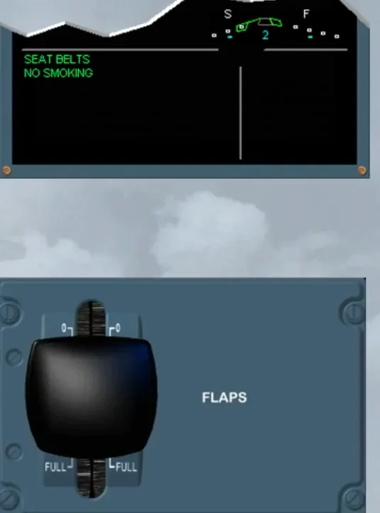
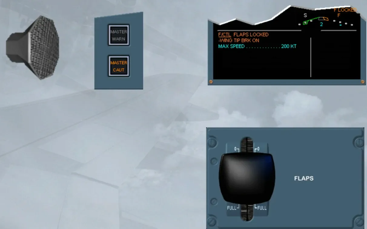
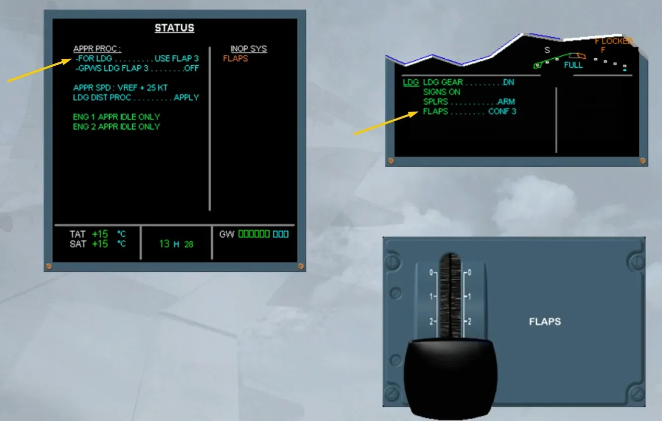
On the slat/flap indicator of the E/WD, observe:
- The “F” legend and the flap triangle have turned to amber, indicating that there is a flap fault
- An amber “F LOCKED” message has appeared above the amber “F”, indicating that the flaps are locked
- The white “S” and the green triangle indicate that the slats have reached the selected position.
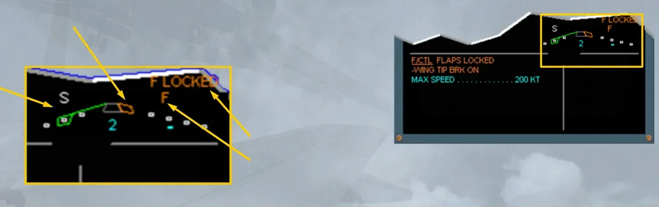
Observe also the amber line WING TIP BRK ON.
The Wing Tip Brakes (WTBs) are hydraulic devices which lock, when activated, the affected surface movement on both wings.
For flaps and slats WTBs hydraulic sources information, refer to the FCOM.
The flaps WTBs, or independently the slats WTBs are activated in case of asymmetry, mechanism overspeed, symmetrical runaway or uncommanded movement of the surface.
Note: Once activated, the WTBs cannot be released in flight.
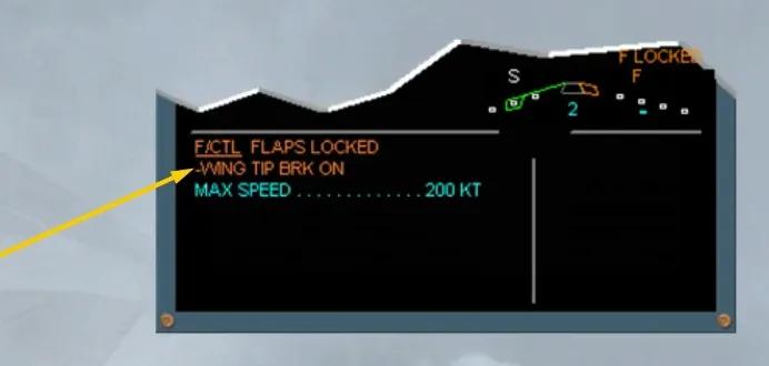
When the flaps wing tip brakes are activated, they do not affect the slats operation and vice-versa.
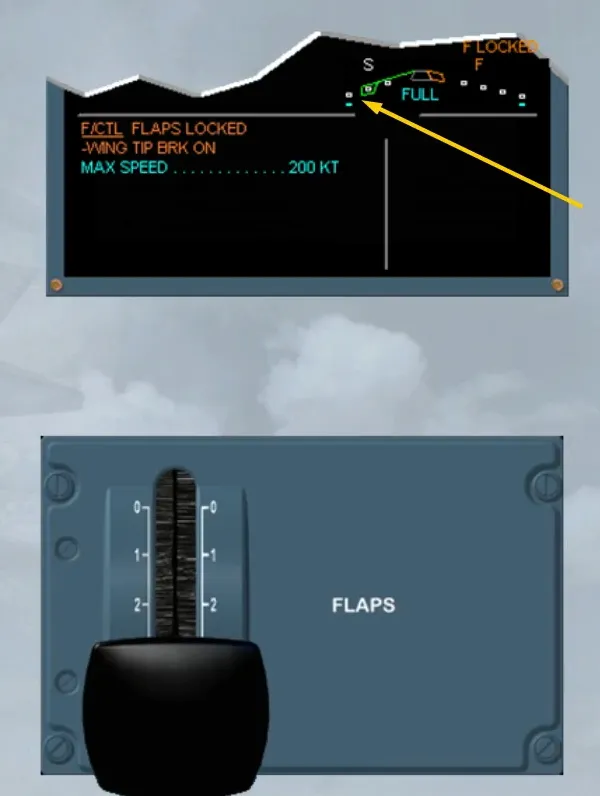
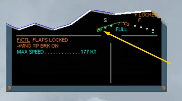
Note: The MAX SPEED indication is the VFE relative to the current position of slats and flaps.
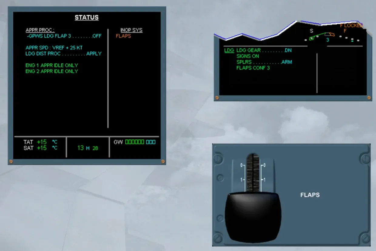
But the procedure will ask you to use the CONF 3 for landing, as it is displayed on the LDG MEMO and on the STATUS page.
So, we did it for you.
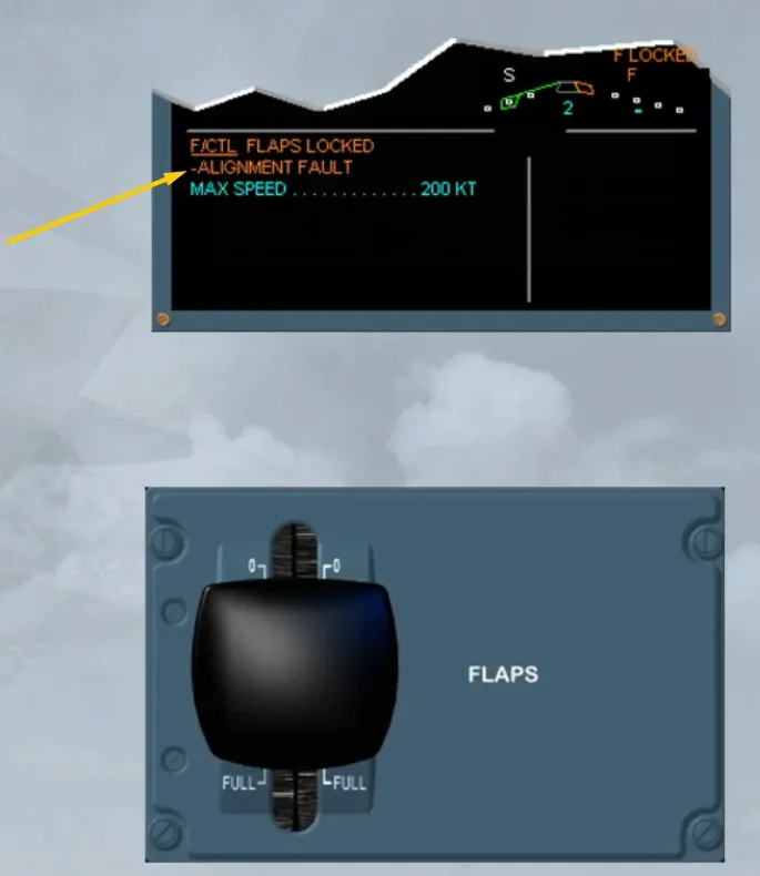
The flaps have a flap disconnect detection system. This system detects attachment failure and inhibits flap operation to limit further damage.
In this case, you will get an ALIGNMENT FAULT. The procedure is similar to the FLAPS LOCKED procedure seen previously.
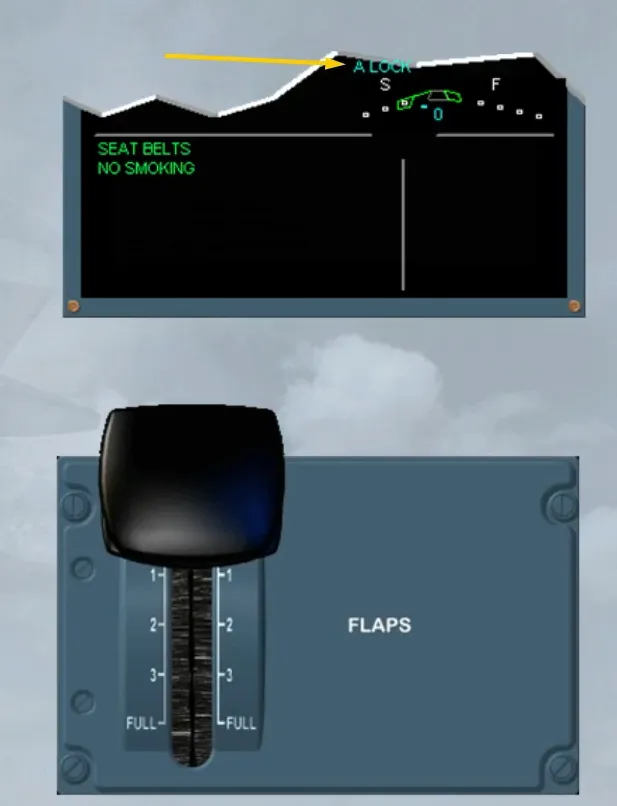
The last protection feature is the slats alpha/speed lock function.
When the FLAPS lever is set to 0, this function inhibits slats retraction in high angle of attack and in low speed conditions. It is indicated by an A LOCK pulsing blue on the slat/flap indicator of the E/WD.
Module Completed