Auto Flight Flight Management
The flight management part of the FMGC performs 4 main functions:
- Navigation based on accurate position
- Flight planning
- Performance prediction and optimization
- Management of the displays.

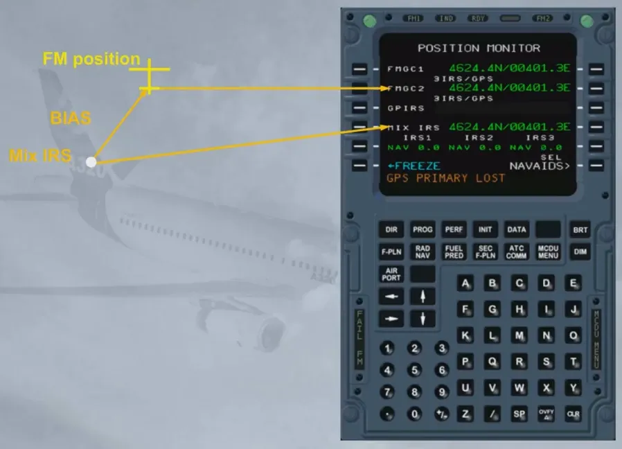
Accurate position computation is one of the essential functions of the FM part of the FMGC. Each FMGC computes its own aircraft position (FM position) from a mixed IRS position and a computed radio position or a GPS position.
The system then selects the most accurate position considering the estimated accuracy and the integrity of each positioning equipment.
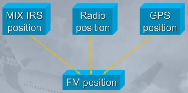
The FMGC computes a mix IRS position from the 3 IRS.
If one IRS fails, each FMGC uses only one IRS (onside IRS or IRS 3).
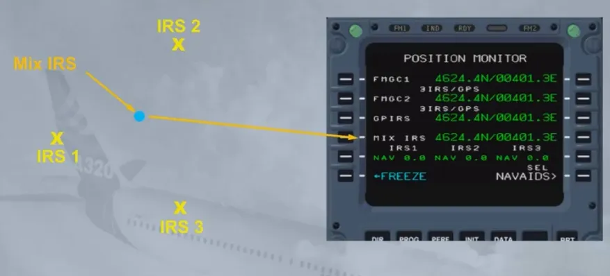
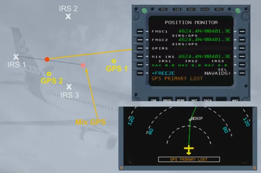
Each IRS computes an hybrid position that is a MIX IRS/GPS position called GPIRS. Only one of the three GPIRS positions is selected by the system according to its figure of merit and priority logic.
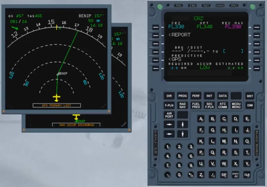
If the GPIRS data does not comply with an integrity criteria, the GPS mode is rejected and the radio position updating is used: GPS PRIMARY LOST is displayed on ND and MCDU scratchpad.
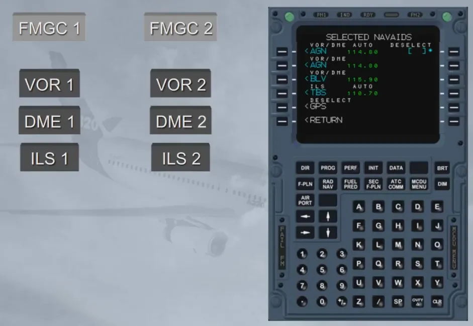
Each FMGC uses onside navaids to compute its own radio position.
The navaids which are automatically autotuned can be:
- DME/DME
- VOR/DME
- DME/ILS (LOC DME - ILS approach selected)
- VOR/ILS (LOC DME - ILS approach selected).
Each FMGC computes a vector from its MIX IRS position to the radio or GPS position: this vector is called BIAS. The BIAS is updated continuously if radio or GPS position is available.
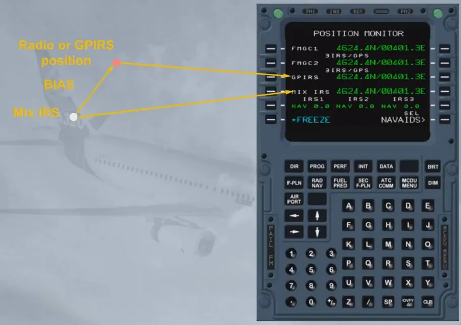
If the radio or GPS position is lost, the BIAS is memorized and added to the MIX IRS position to compute the FM position.
Note: At take off, the FM position is updated to the runway threshold position memorized in the data base.
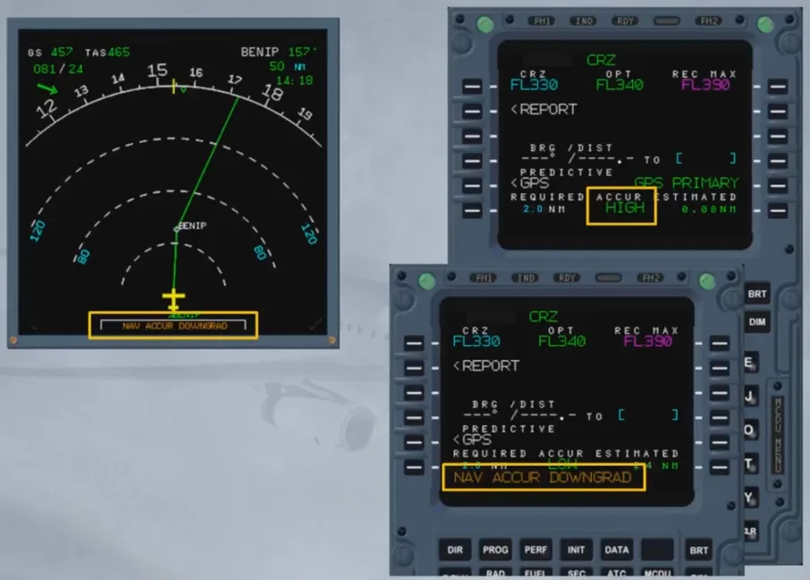
Depending on the navigation mode used by the system (IRS/GPS, IRS/DME/DME, IRS/VOR/DME or IRS only) the FMGC computes an Estimated Position Error (EPE).
The EPE is then compared to the Required Navigation Performance (RNP) defined by the airworthiness authorities as a nominal error tolerated within a flying area (TMA) or along a given flight plan leg.
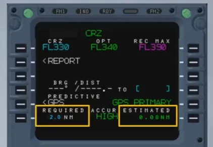
If the EPE is lower than RNP, accuracy is HIGH. If the EPE is higher than RNP, accuracy is LOW.
When the accuracy switches from HIGH to LOW, a message NAV ACC DOWNGRAD is displayed on ND and on MCDU scratchpad.
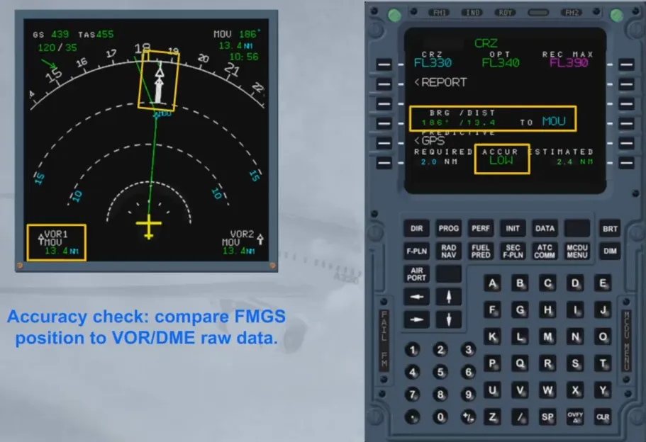
When the GPS function is lost, the crew must check the position accuracy using raw data information if available.
The position accuracy cross check using raw data information has to be done:
- Periodically during the flight (unless GPS is primary)
- Systematically when GPS PRIMARY LOST message comes up
- Systematically when NAV ACC DOWNGRAD message comes up.
Keep in mind that HIGH/LOW messages are computed on estimated data:
therefore even if LOW is displayed, the accuracy check may be positive.
For flight planning, the pilot inserts the following data into the FMGS via the MCDU:
- The lateral part of the F-PLN
- The vertical part of the F-PLN (speed, time, altitude constraints or step climb). In fact, 2 F-PLNs can be inserted in the FM:
- A primary one, used for the legs to be flown and
- A secondary one, used to prepare an alternative departure or arrival or a diversion, which can be activated by the pilot whenever required.
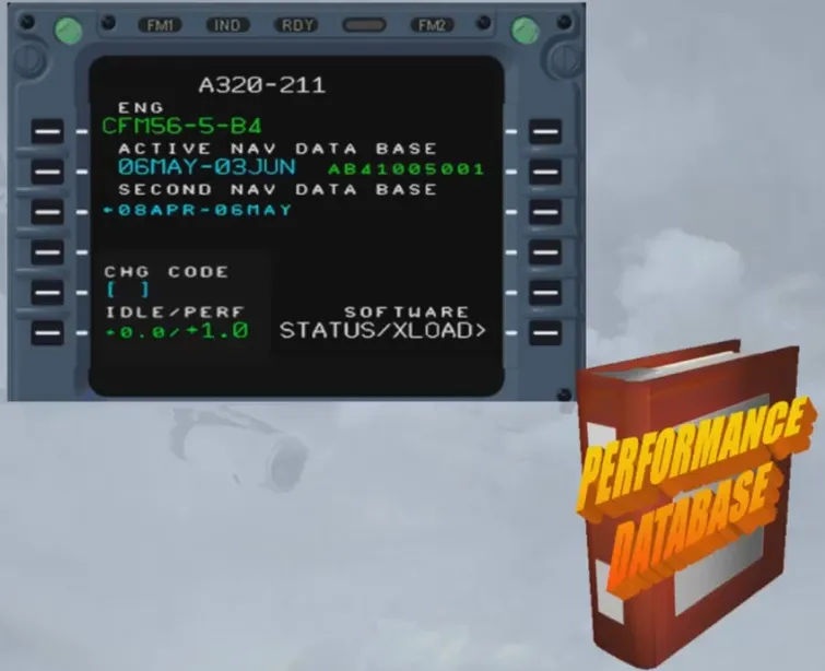
The Flight Management system, or FM, uses two databases to perform its computations:
- A navigation database, and
- Performance database.
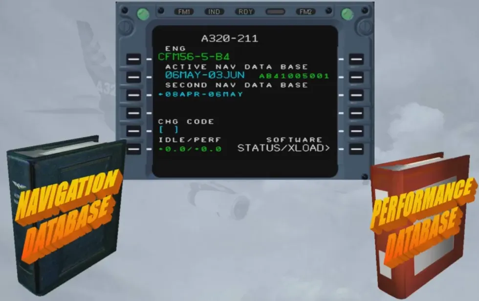
The navigation data base, or nav database, contains all the necessary information for the lateral flight plan, such as routes, airways, VORs, NDBs, waypoints and airports.
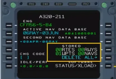
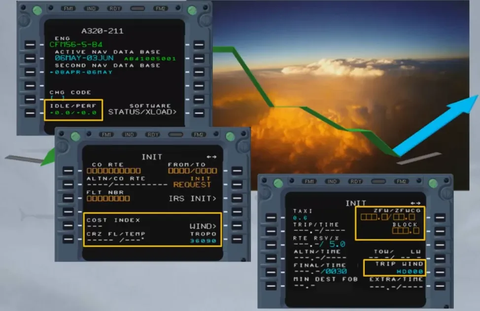
The navigation database is updated every 28 days and its currency and validity is checked on this page during the preflight. Notice there is an active database and a secondary or second database.
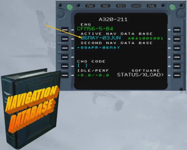
The secondary (second) database is either the previous or the next database. Databases are loaded two at a time so that if the first one expires away from a maintenance base, the pilot can activate the second one before departure the next day.
The performance database, or perf database, contains the aircraft performance model and is used to optimize the flight plan and to obtain predictions such as ETAs, EFOB etc …
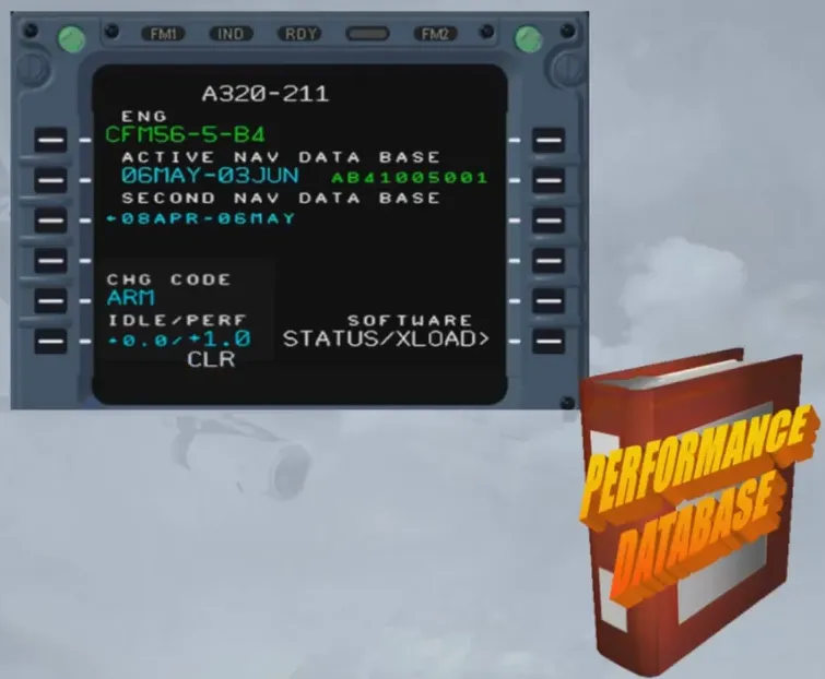
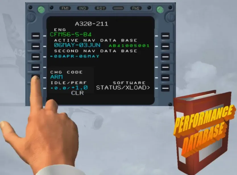
The change code is only displayed in the PREFLIGHT and DONE phases. When the code has been inserted, the IDLE and PERF factors turn to blue. This allows the engineering team to modify these factors, in order to take engine and aircraft aging into account and to adapt fuel predictions to actual fuel consumption.
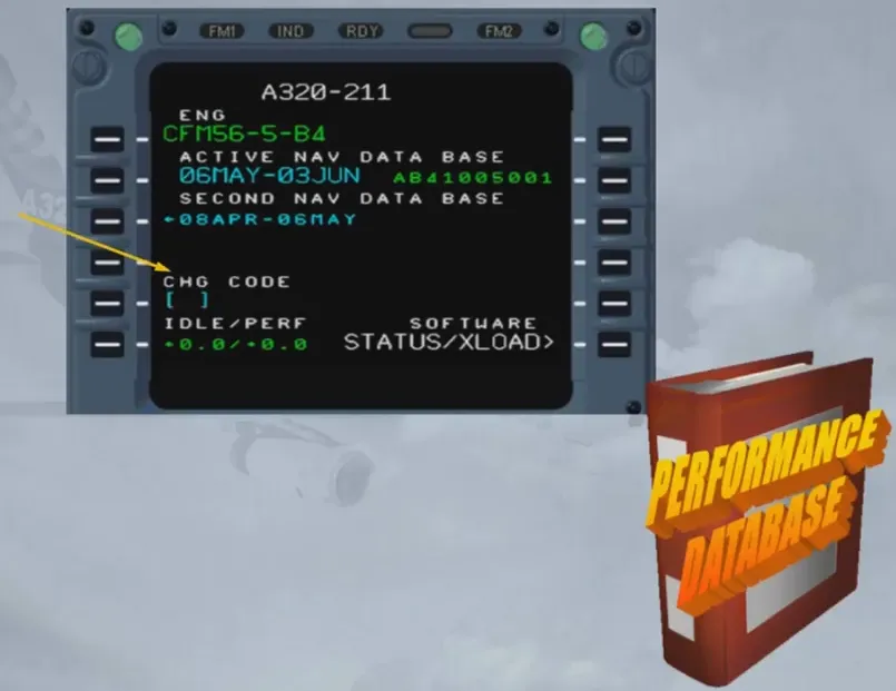
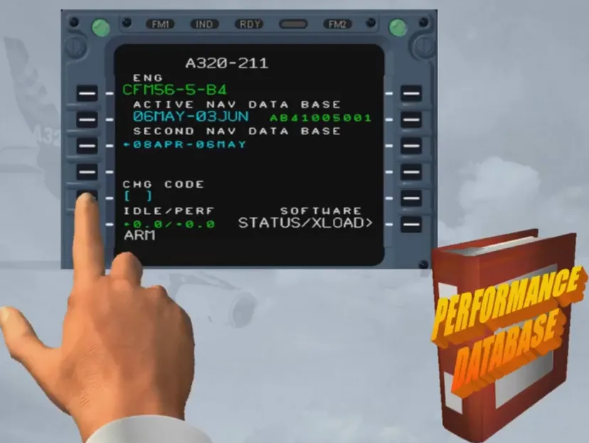
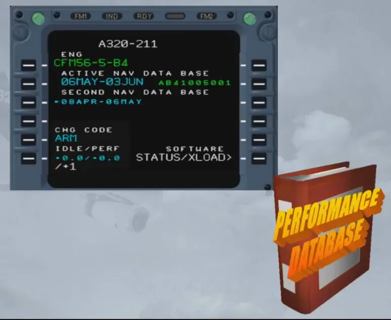
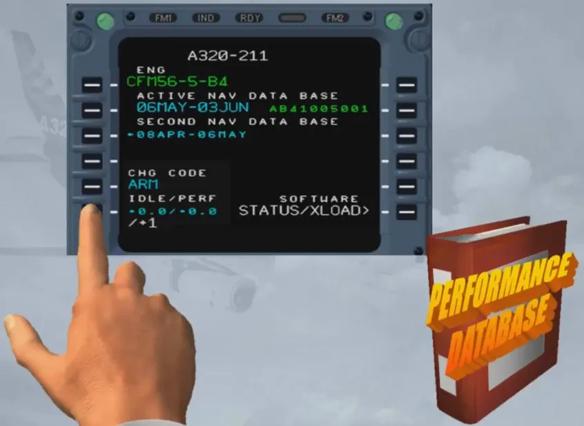
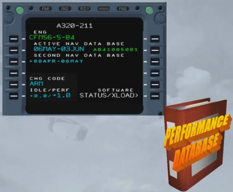
Note: A positive IDLE factor gives an earlier T/D and a negative one delays the T/D. The PERF factor relates to a percentage which means that the airline flight operations have evaluated a fuel deviation from the basic performance model. Clearing the code will lock the change.
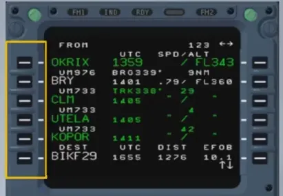
The lateral flight plan includes:
- Departure
- En-route
- Arrival
- Alternate.
These elements are defined by waypoints and legs. The FMGC automatically strings the legs in sequence.
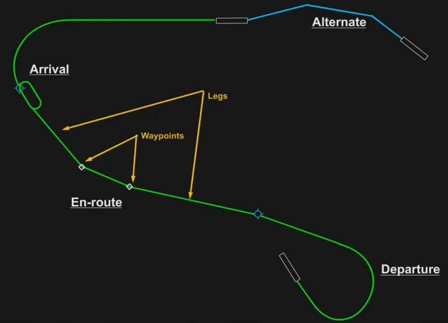
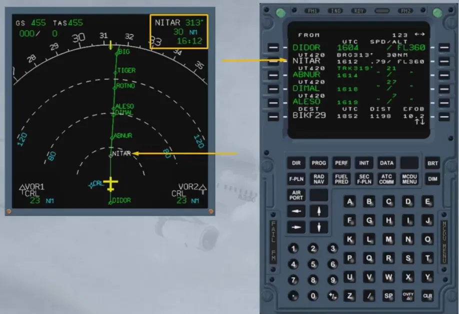
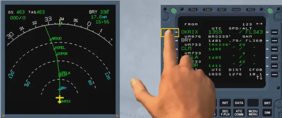
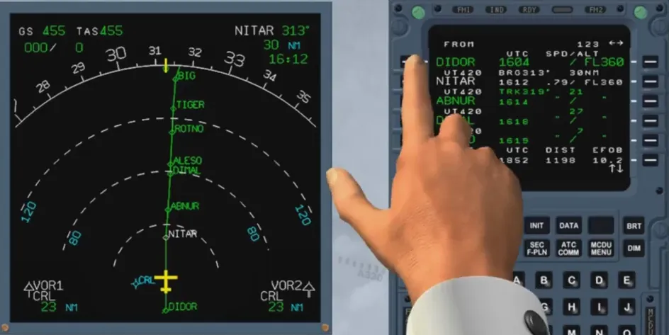
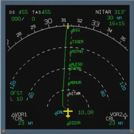
When flying in NAV mode (navigation managed by the FMGC), the aircraft is guided on a leg (called active leg) defined by a FROM and a TO waypoint.
The TO waypoint is depicted in white on the MCDU and on the ND as well, in the top-right hand corner.
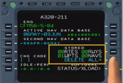
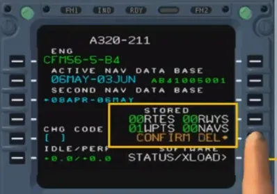
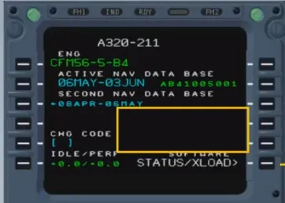
During preflight, the first thing that we do is confirm the correct information on the status page. So, the loaded database of FM1 and FM2 must be identical…
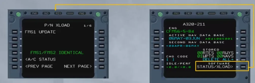
… and the stored data, added by the previous crew may be cleared, as shown.
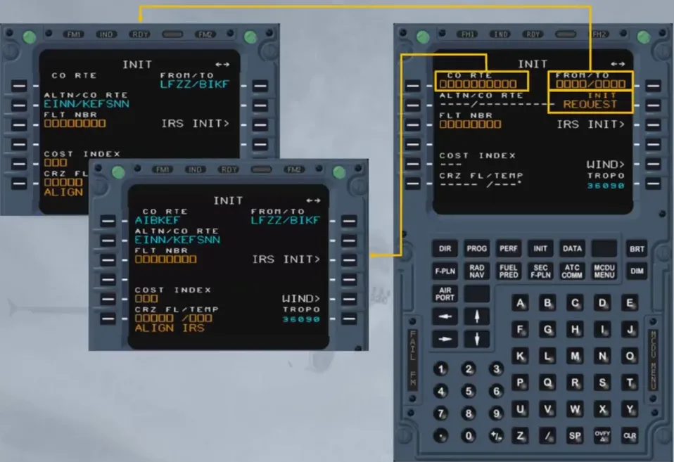
We are then ready to begin programming the route of flight, this is called initializing the flight plan.
This initialization of the F-PLN is done through the INIT page A. We will call it for you.
The pilot enters the flight plan in either three ways:
- By inserting an origin/destination pair and then manually selecting a departure, waypoints, airways and an arrival, or
- By inserting a company route name stored in the database, or
- By sending a request for an active F-PLN initialization (see FANS course).
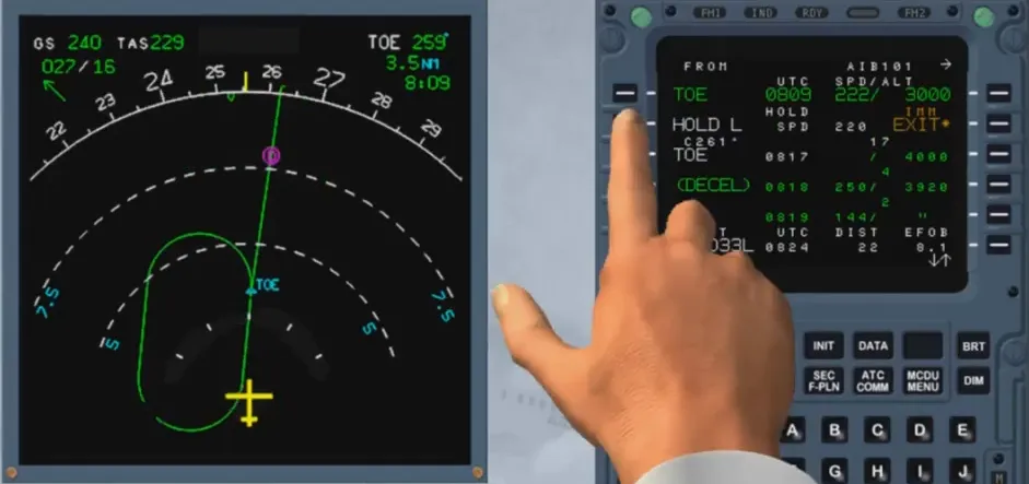
The F-PLN once inserted can be modified by two types of revisions:
- Lateral revisions which have an immediate effect on the active F-PLN
- Lateral revisions that lead to a temporary F-PLN.
These revisions are selectable from the left keys on the MCDU.
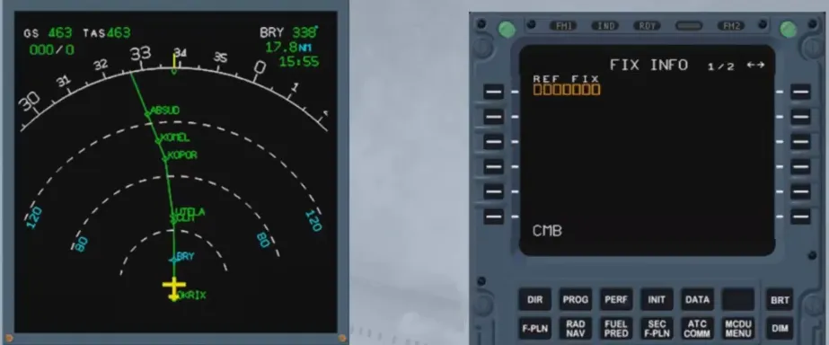
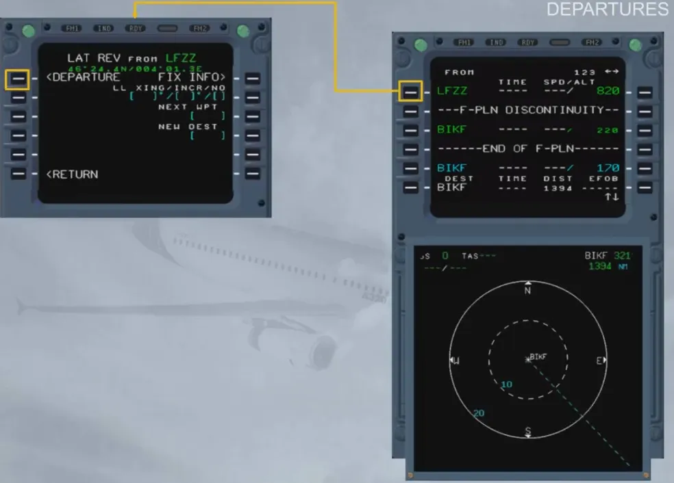
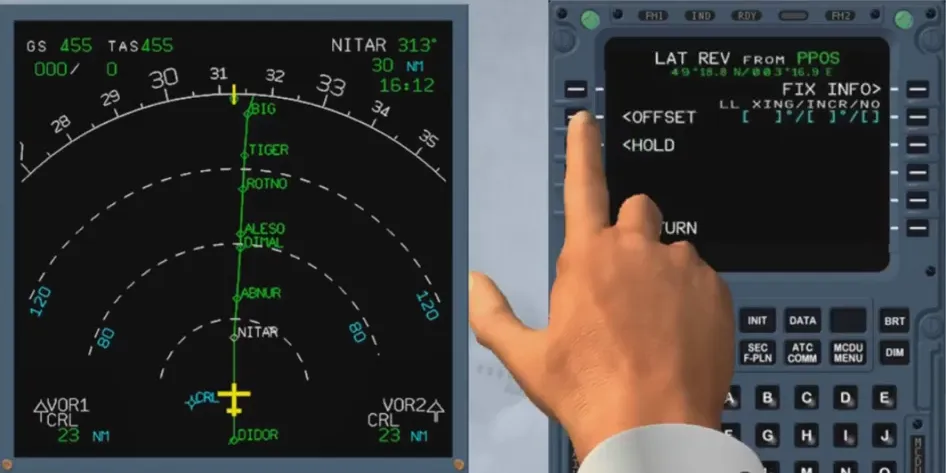
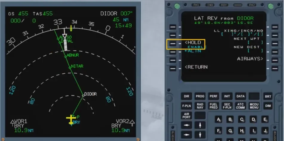
A lateral revision at present position (PPOS) allows the access to the FIX INFO page.
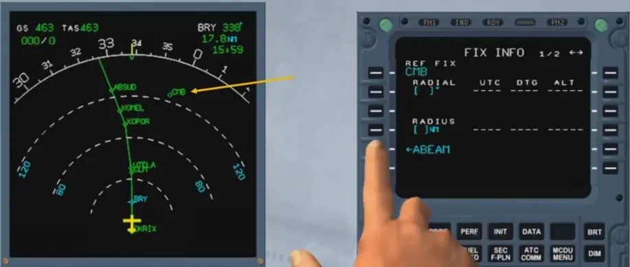
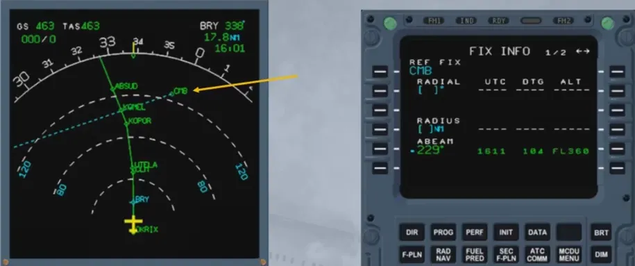
On this FIX INFO page, if a reference is entered, as shown, it is also shown on the associated ND.
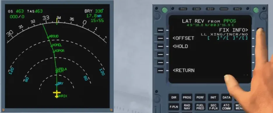
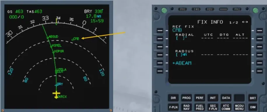
Then a radial or a radius can be inserted or ABEAM prompt can be selected, as here. After computation, the predictions are shown and if now the associated key is pressed again, an interception point will be added on the flight plan.
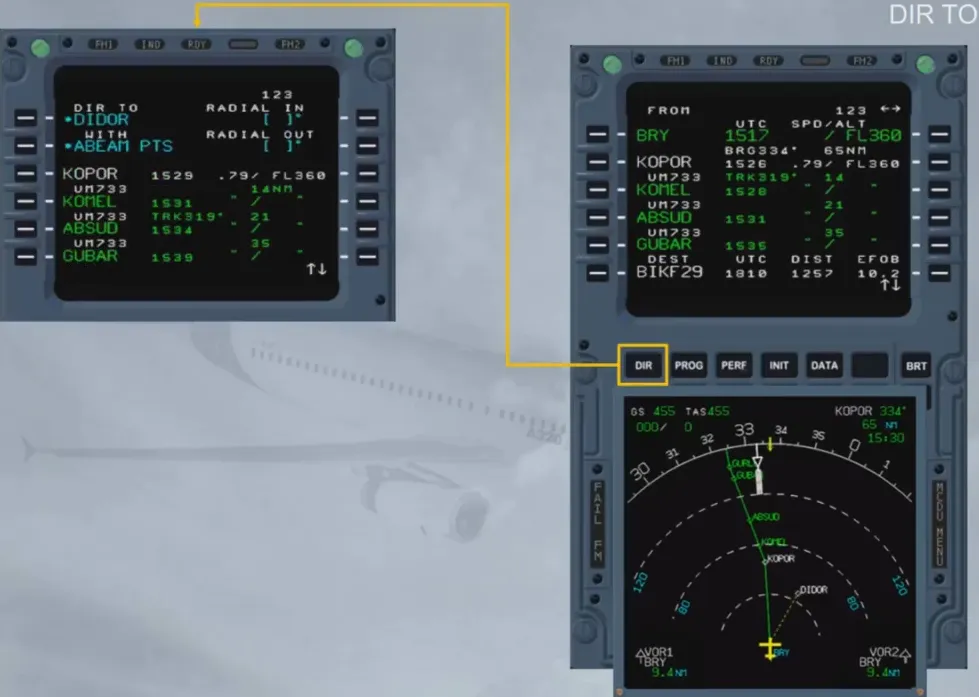
The “DIRECT TO” function is an immediate effect lateral revision which allows the aircraft to fly from the present position directly to a waypoint (with abeam points displayed along the track if ABEAM PTS is selected) or to intercept an inbound or outbound radial to/from this waypoint.
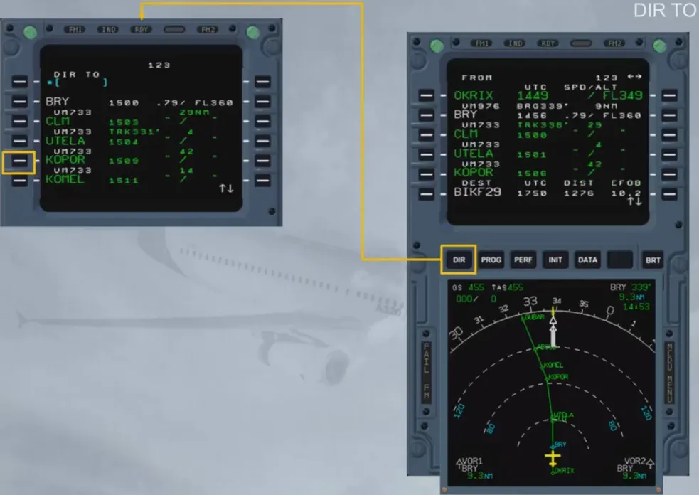
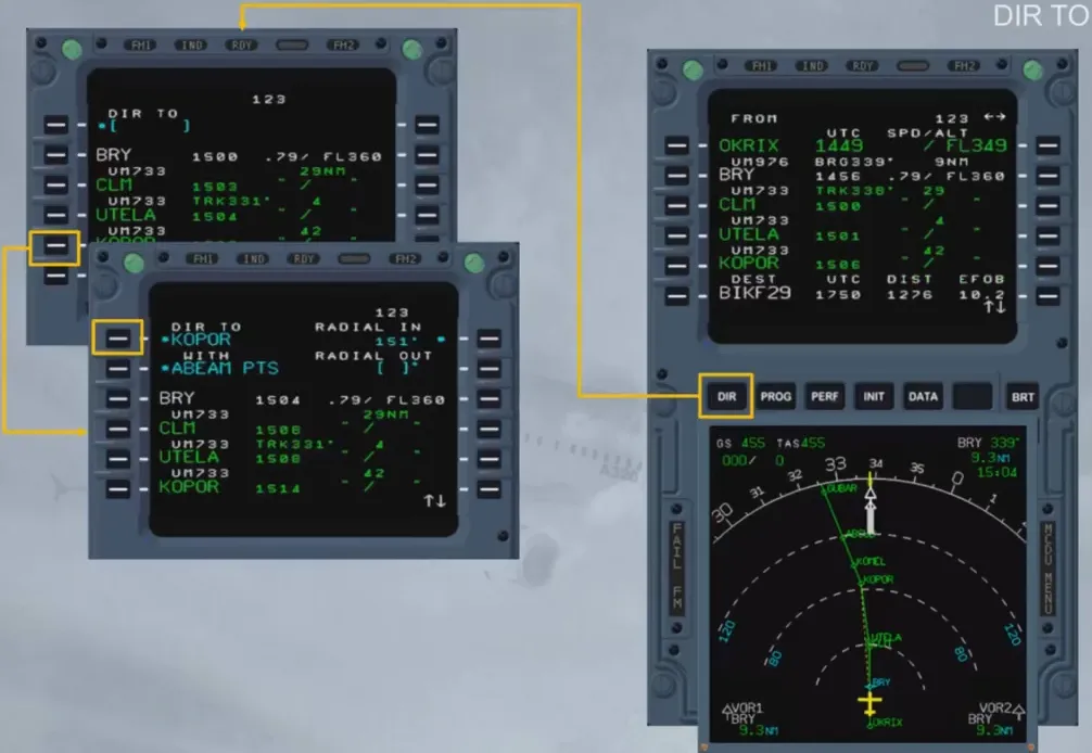
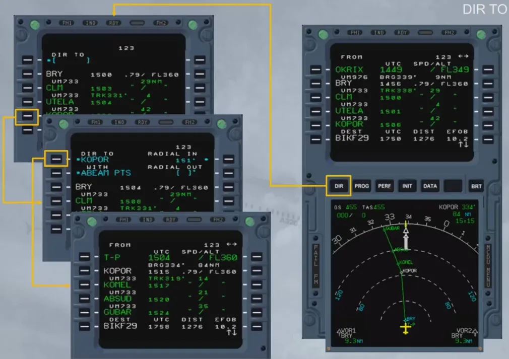
If the waypoint does not belong to the F-PLN, it has to be inserted via the scratchpad.
Waypoints which can be inserted are waypoints from the database or waypoints which are defined by the crew (place/bearing/distance, place-bearing/place-bearing).
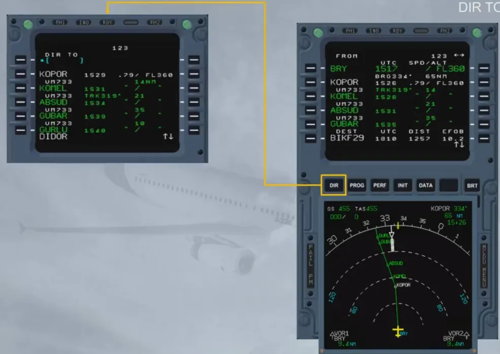
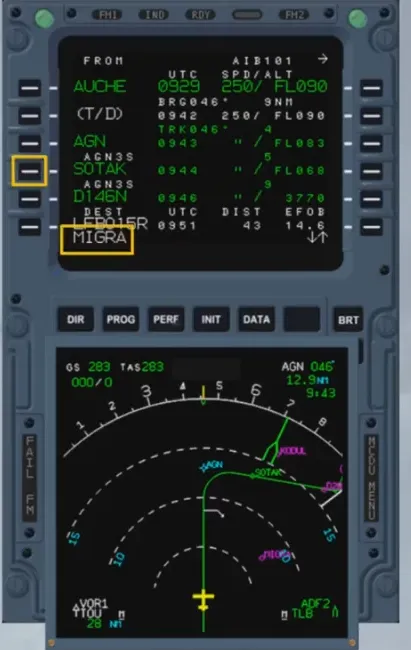
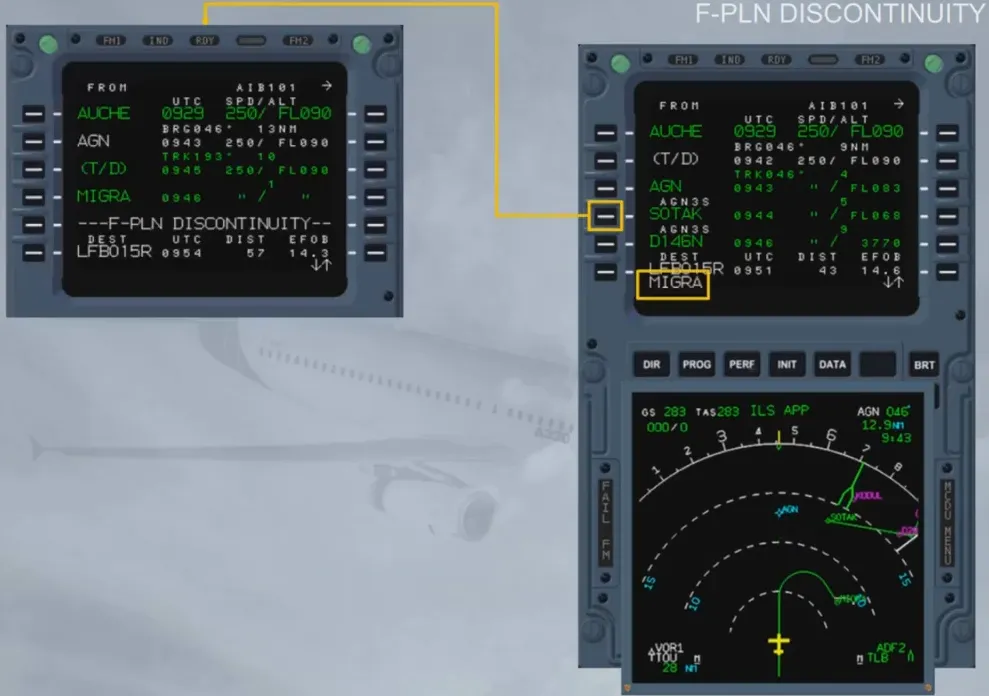
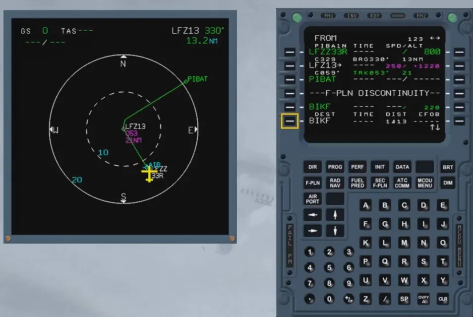
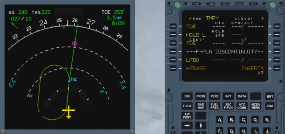
Deleting a waypoint in the F-PLN will create a F-PLN discontinuity in the active F-PLN.
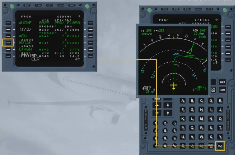
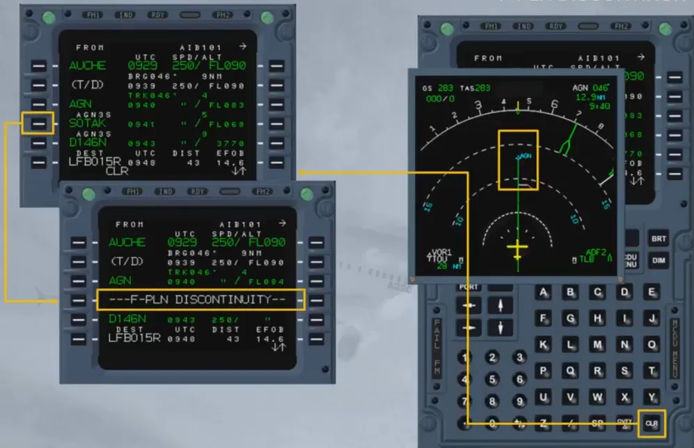
Adding a waypoint in the F-PLN will create a F-PLN discontinuity.
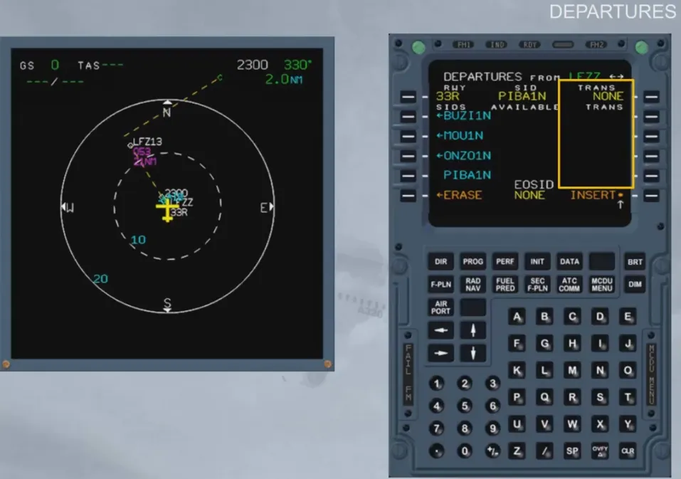
Using a lateral revision at origin, the pilot can insert or modify the take off runway, the SID and the en-route transition through the departure revision.
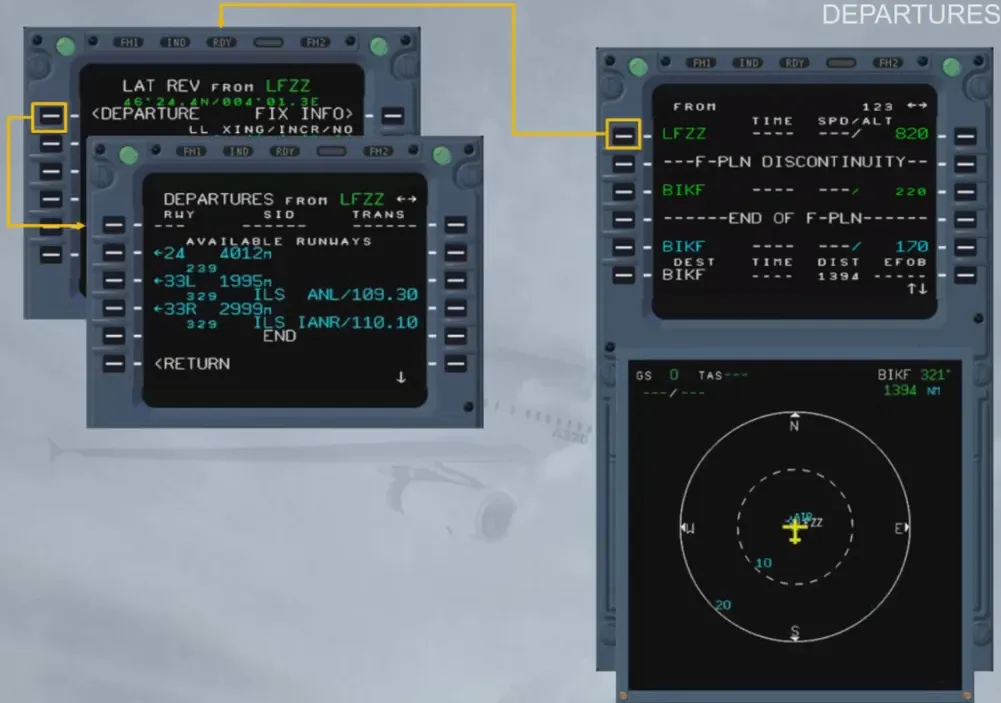
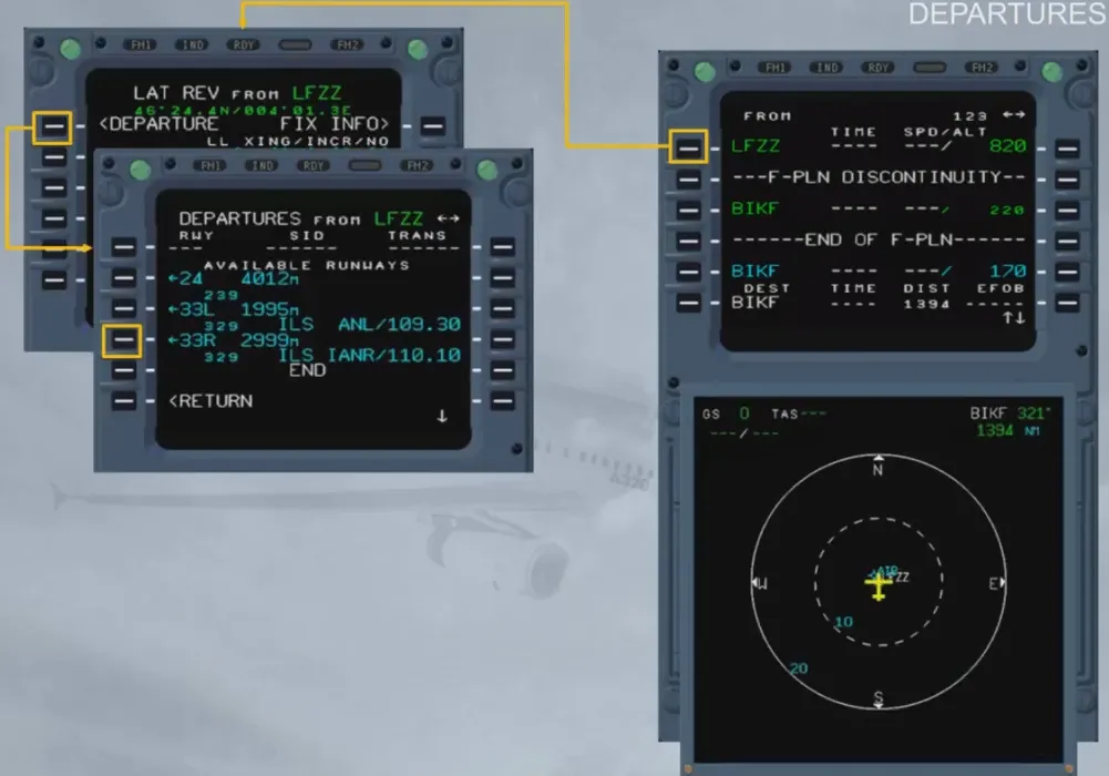
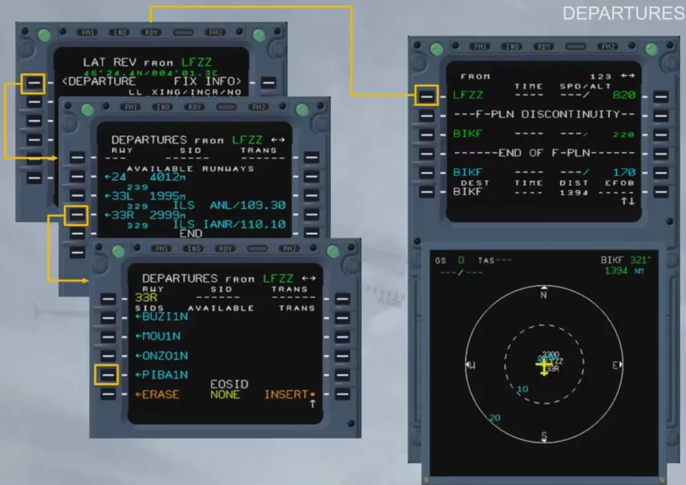
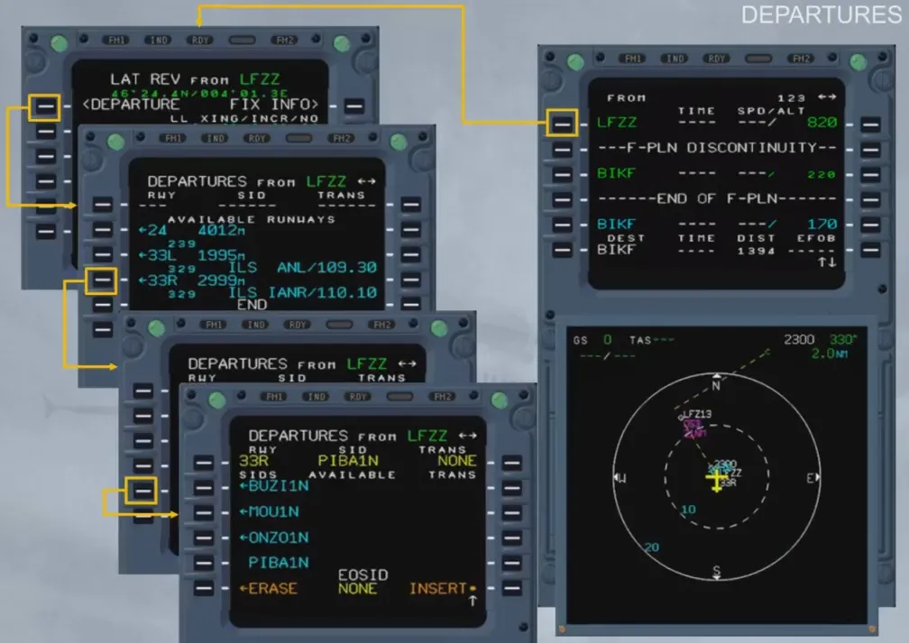
The en-route transitions (TRANS) are the various possible trajectories defined between the last waypoint of the SID and the first en-route waypoint.
There is no transition available in this example.
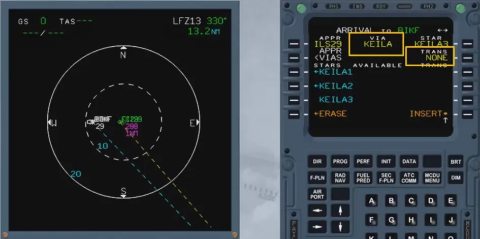
A lateral revision at destination (LSK 6L), gives access to the arrival data.
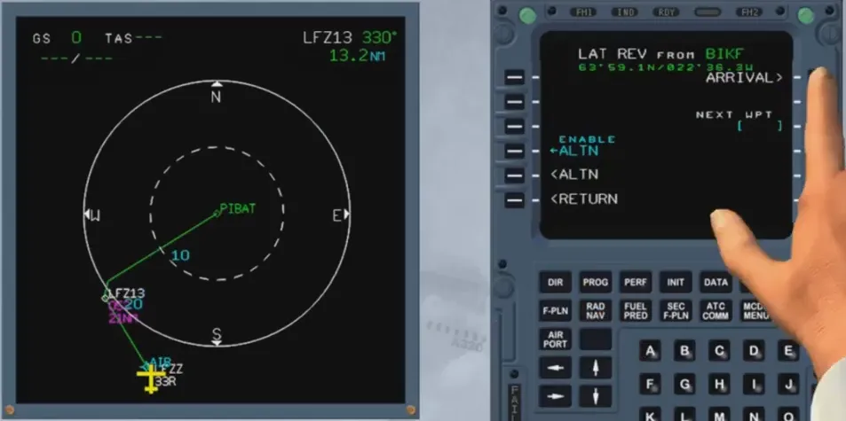
The runway and the type of the approach can be chosen…
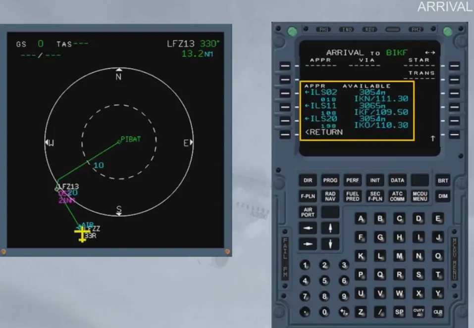
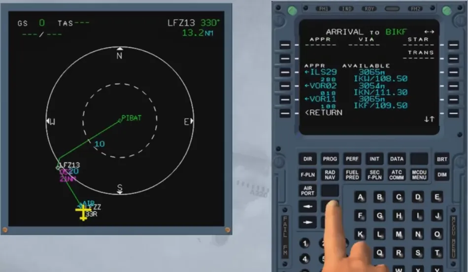
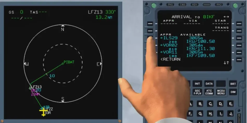
… as well as the STAR …
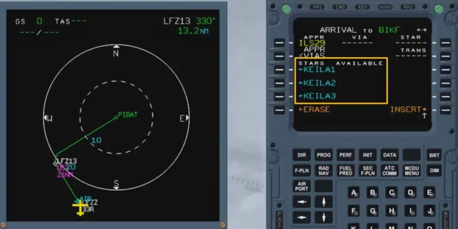
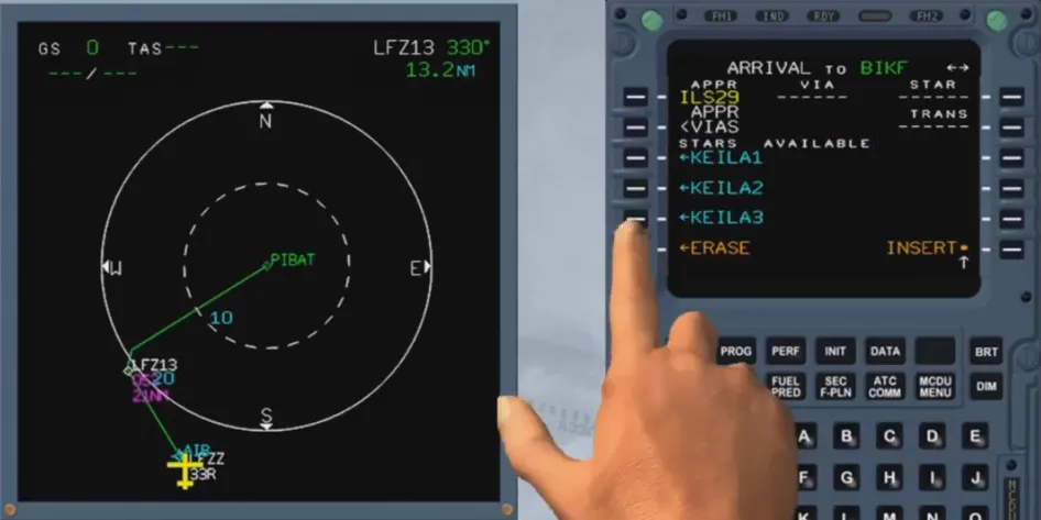
… the VIA and the en-route transition (if any).
APPR VIAS are the various possible trajectories defined between the last point of the STAR and the first point of the approach.
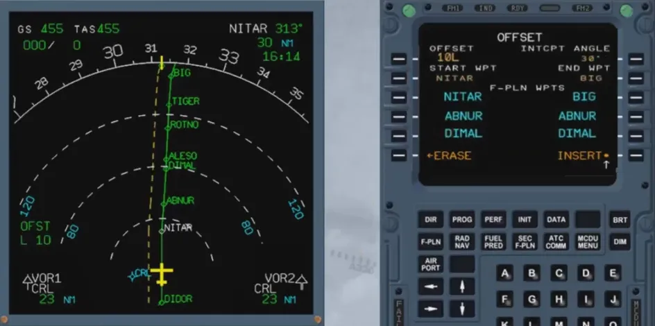
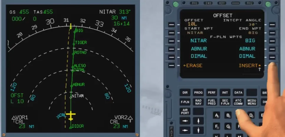
The revision at any waypoint (here at the FROM waypoint or PPOS) allows the pilot to select the OFFSET prompt, that displays the OFFSET page where he may define a lateral offset to the left or to the right of the active F-PLN. Also, defaulted indications are displayed like the START WPT, and they can be modified by a new selection.
The offset value inserted is in NM
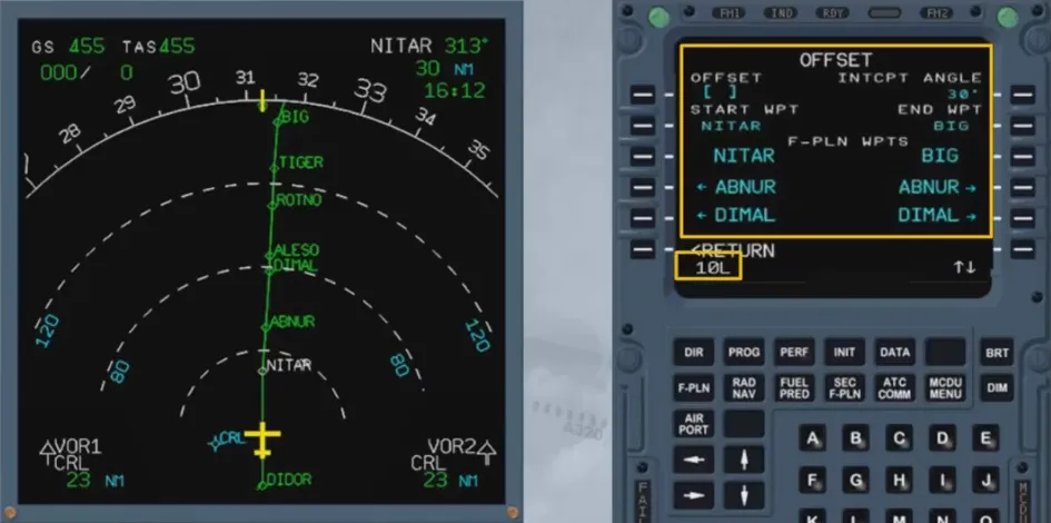
Once the offset has been inserted, the initial F-PLN appears as a dotted line.
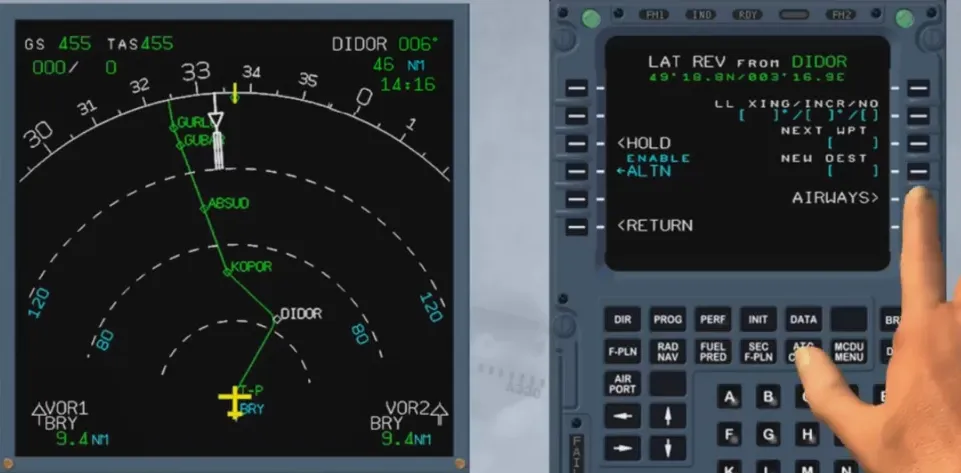
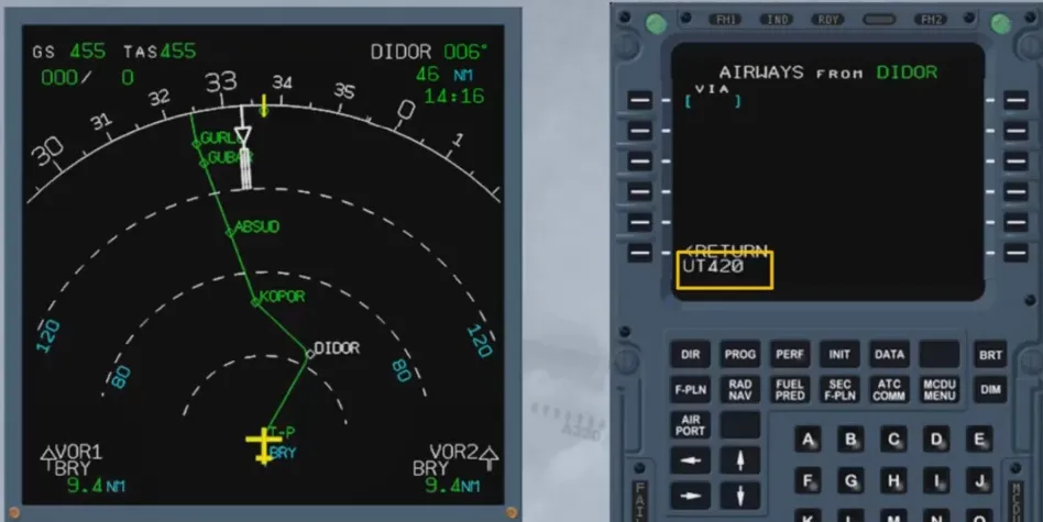
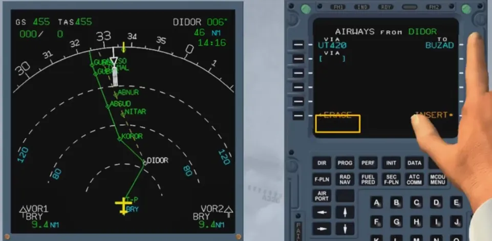
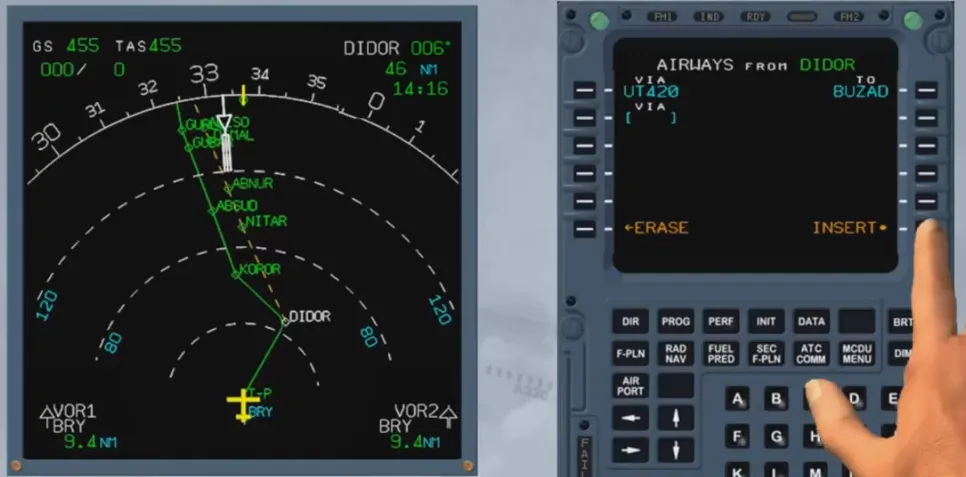
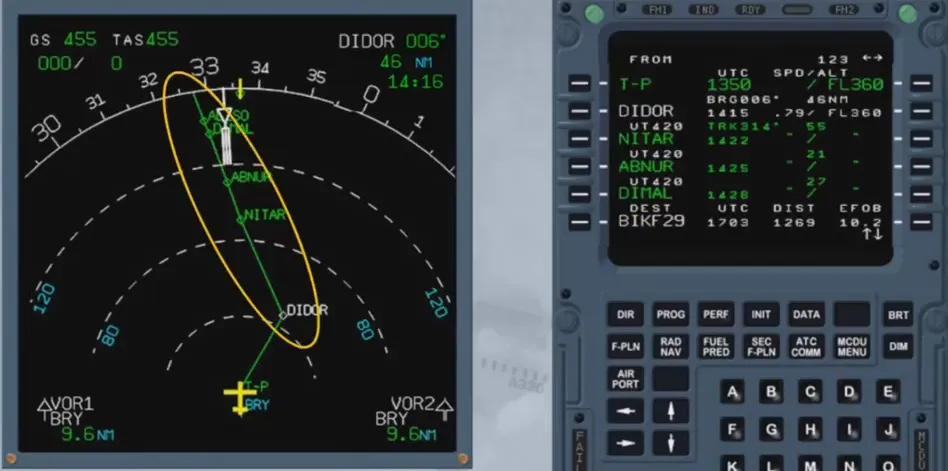
A lateral revision at a waypoint allows the pilot to insert into the active F-PLN up to five segments of airways starting at the revised waypoint.


The AIRWAYS page is accessed by the LSK 5R on the waypoint LATERAL REVISION page. The revision is done for each segment by first inserting its airway ident, and then by inserting its ending point.
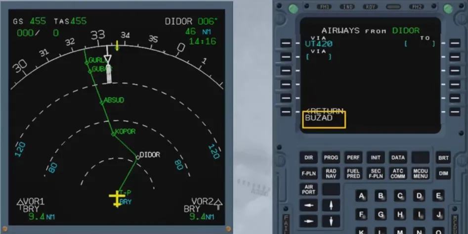
After the insertion in the F-PLN is completed, some cleaning may be required.
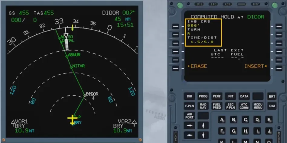
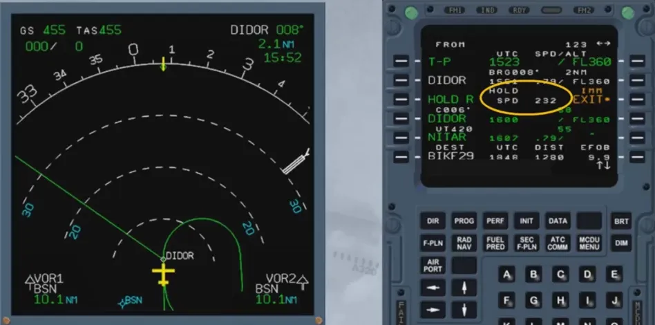
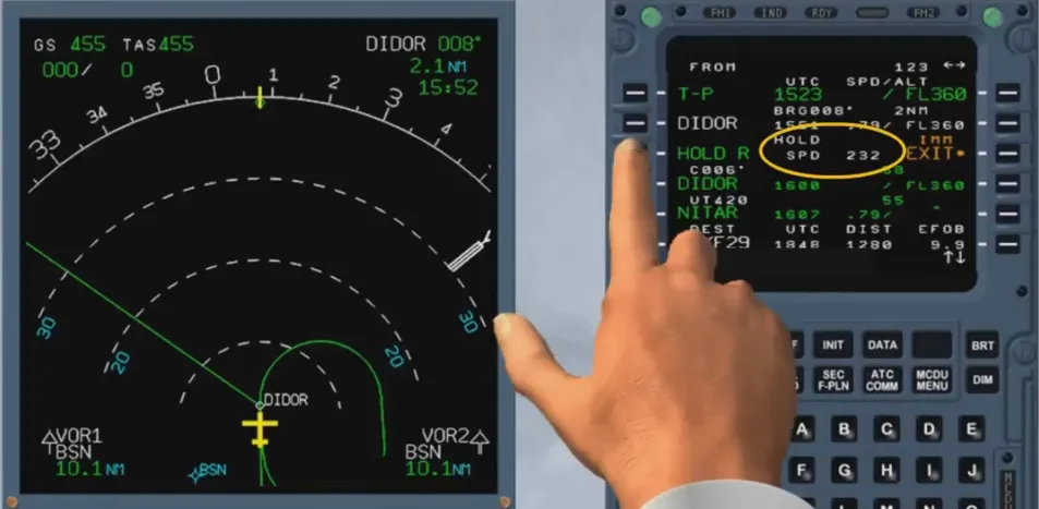
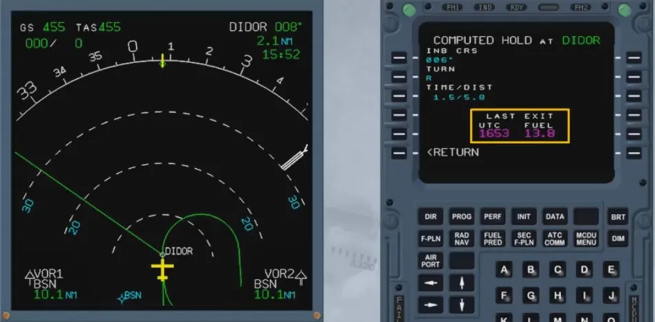
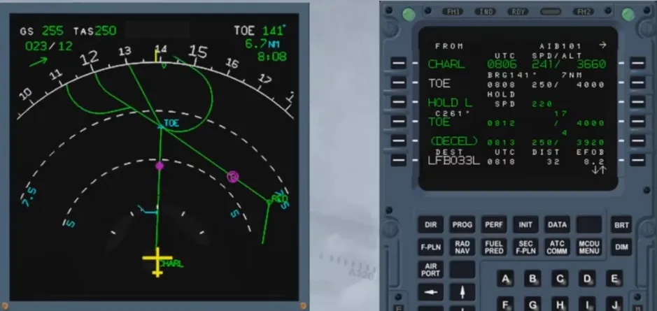
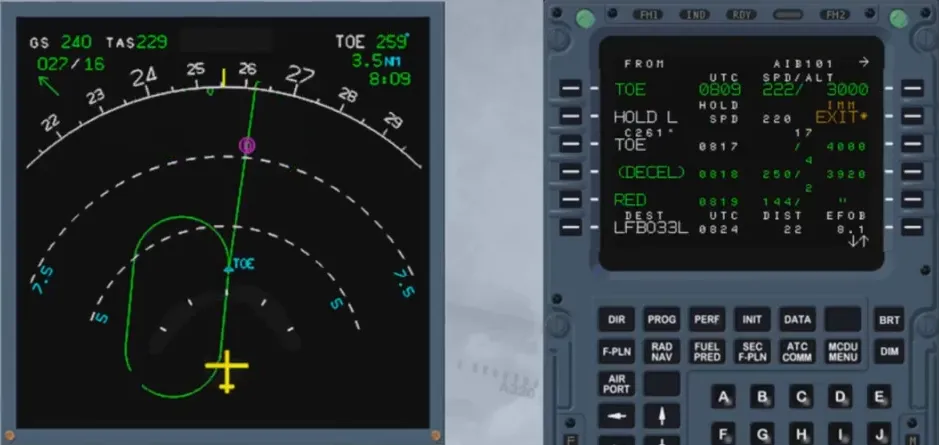
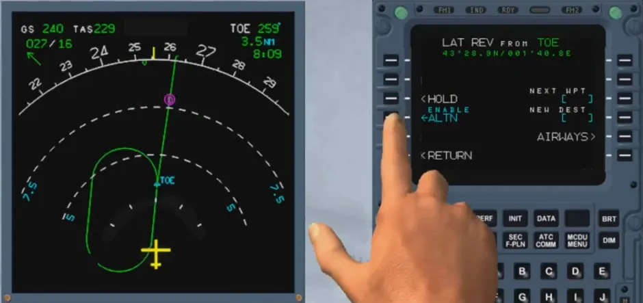
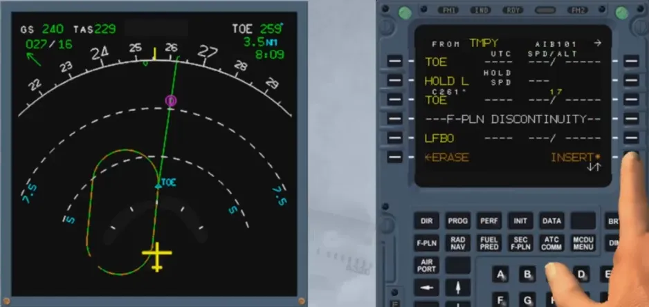
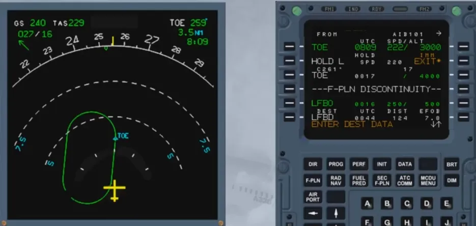
A holding pattern can be inserted from a revised waypoint:
- Using a DATABASE HOLD AT: the parameters of the holding pattern are stored in the navigation database
- Using a COMPUTED HOLD AT: the parameters of the holding pattern are defaulted to predetermined values which can be modified.
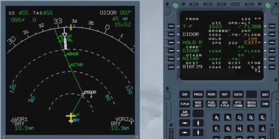
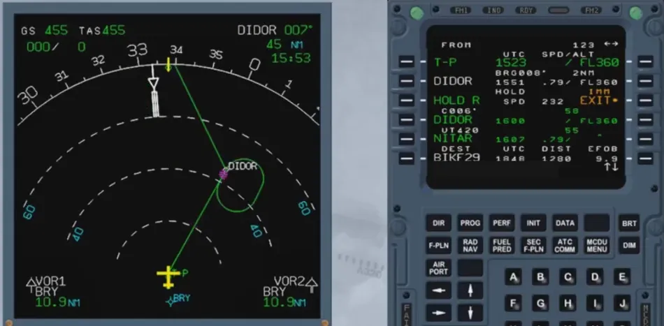
Once a holding pattern is inserted in the F-PLN, it is initially not taken into account by the FMGC for prediction computation as the system does not know if the pattern will be flown. Once entering the holding pattern, the system considers that only one pattern will be flown.
Prior to entering the holding pattern:
- If managed speed is active and NAV mode engaged, the target speed will automatically be set to the computed holding speed, or
- If the speed is selected, a message “SET HOLD SPEED” will be displayed on the MCDU and PFD.
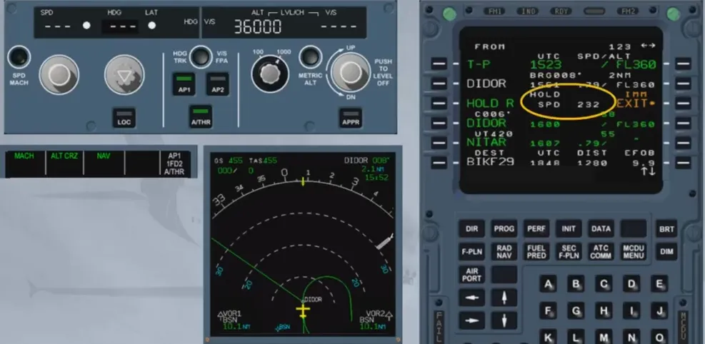
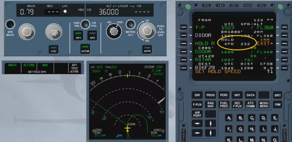
The holding speed is the lowest of:
- Maximum endurance speed
- ICAO limit holding speed
- Speed constraint (if any). The FMGC predicts the latest estimated time at which the aircraft must exit the holding pattern and the estimated amount of fuel so as to fly to destination according to fuel policy (extra fuel = 0).
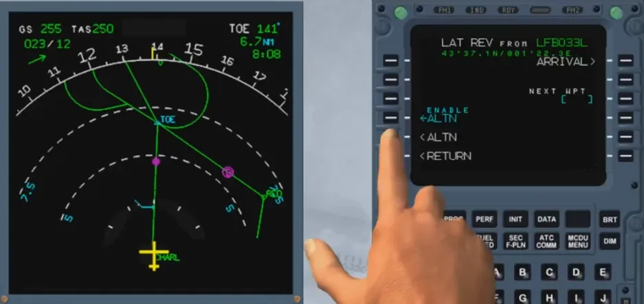
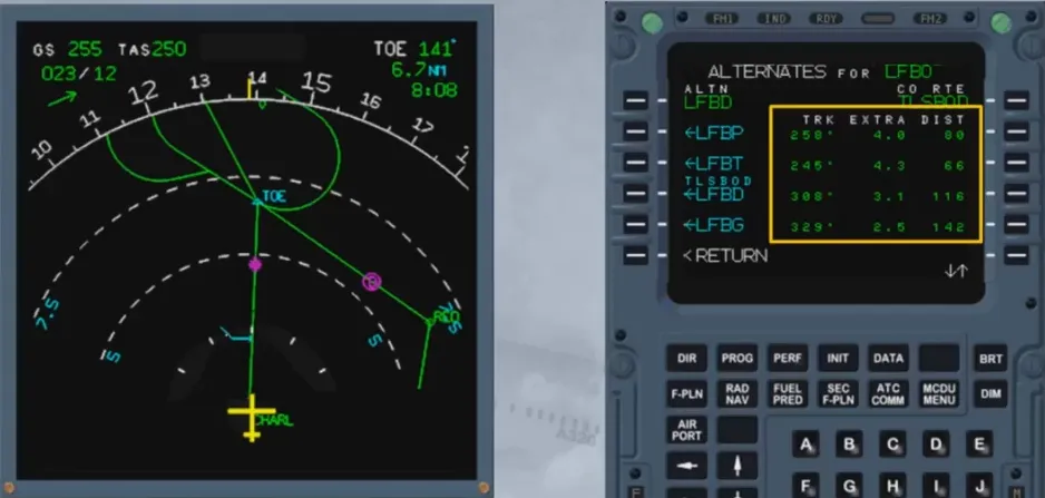
This revision allows the pilot to select an alternate airport. Several alternate airports may be stored in the database.
The alternate page displays the track, distance and extra fuel corresponding to the different alternate airports. This assists the pilot in choosing the alternate airport according to weather conditions or fuel considerations.
A lateral revision allows the pilot to initiate a diversion to the alternate by selecting the alternate F-PLN from any revised waypoint belonging to the active F-PLN. A F-PLN discontinuity will be displayed between the revised waypoint and the first waypoint of the alternate F-PLN.
The vertical F-PLN is defined by:
- Strategic data affecting the overall F-PLN
- Tactical data affecting a given phase of flight
- Weather data.
This data is either inserted by the crew or stored in the performance data base.

The strategic data is:
- Idle, Performance factor
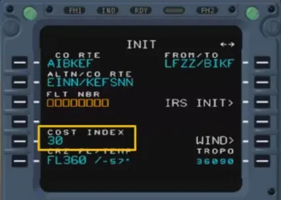
- Cost index
- CRZ FL and temperature, tropopause
- Wind or trip wind
- ZFW, ZFWCG, block fuel.
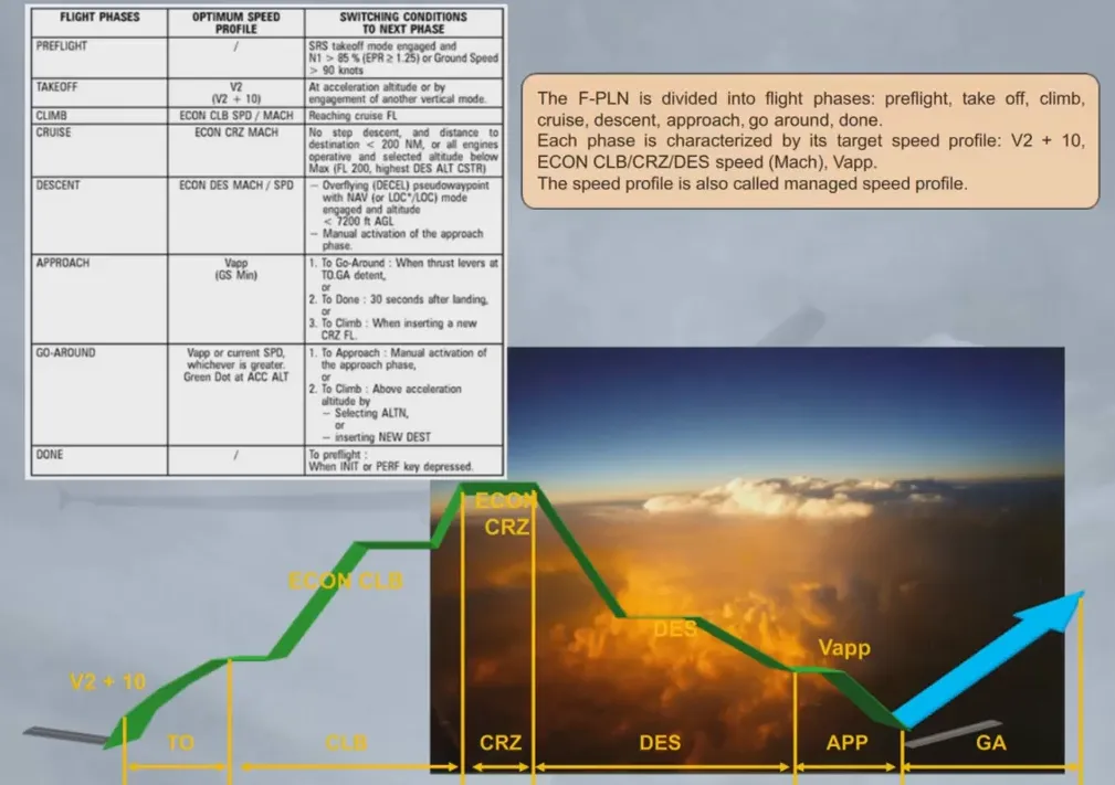
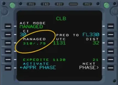
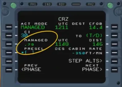
The F-PLN is divided into flight phases: preflight, take off, climb, cruise, descent, approach, go around, done.
Each phase is characterized by its target speed profile: V2 + 10, ECON CLB/CRZ/DES speed (Mach), Vapp.
The speed profile is also called managed speed profile.
The vertical F-PLN includes vertical constraints assigned at waypoints (altitude and/or speed), which are stored in the database or entered manually by the crew.
An other constraint, the Requested Time of Arrival, or RTA, at the revised waypoint may be entered by the crew.

Also part of the vertical F-PLN are constant MACH segments, defined by a desired MACH value and its associated starting point.
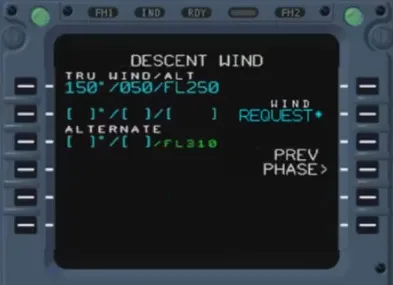
The vertical F-PLN also includes weather data inserted by the crew:
- Temperature and wind for CRZ
- Wind for CLB and DES
- Also, on the APPR PERF page.
The FMGC optimizes the cost of operation computing ECON speed/Mach for each phase of flight. These speeds/Mach are computed as a function of:
- Gross Weight (GW)
- Cost Index (CI)
- Cruise Flight Level (FL)
- Winds/temperature models and actual ones
- Performance data.
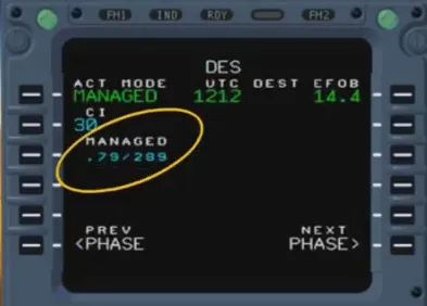
Cost Index (CI) is the ratio of flight time cost to fuel cost. It is used to compute the best ECON speed or Mach:
- Cl = 0 corresponds to minimum fuel consumption or maxi range
- Cl = 999 corresponds to minimum time.
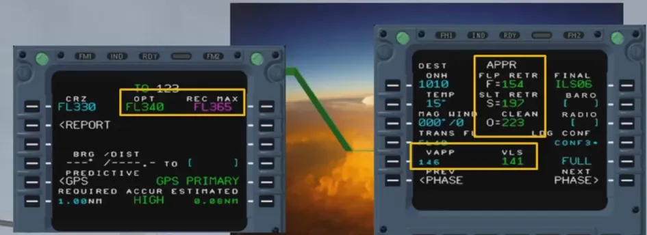
Additionally, the optimization function provides the following data:
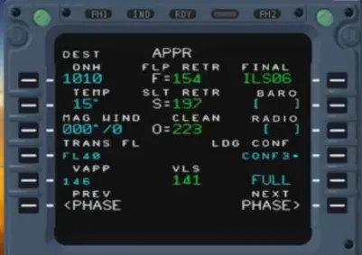
- Maneuvering speed for take off, approach and go-around (O, S, F)
- Approach speed and VLS in landing configuration
- Optimum flight level and recommended max altitude. The optimum FL is the one at which the aircraft incurs the lowest cost (for given F-PLN, GW and CI).
Note: These terms will be discussed in more details in the performance course.
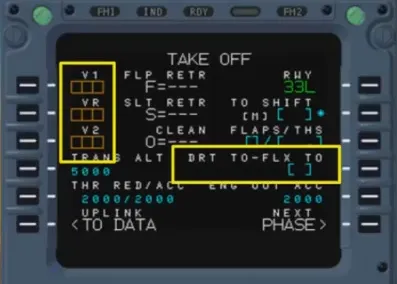
Take off speeds V1, Vr, V2 as well as the FLEX TO temperature or DRT TO level are manually inserted by the crew in the MCDU.
The FMGC computes predictions for the primary and secondary F-PLN whenever the lateral and vertical F-PLN are completed and when all strategic and tactical data is inserted.
These predictions comprise Top of Climb (T/C) and Top of Descent (T/D), Fuel, speed change etc.

Predictions are provided on ND by symbols, in the current active AP modes:
- If NAV mode is active, they are displayed along the active F-PLN
- If HDG/TRK mode is active, they are displayed along the track line.
Decel point. Altitude constraint (amber if predicted missed, white if disregarded). Speed change. Interception point of the descent profile. Top of CLB/LVL OFF. Top of DES/Start of CLB.

The PFD provides the guidance targets on each dedicated scale:
- Speed target
- Vertical deviation
- Altitude target
- HDG or TRK target.
Note: For NPA a lateral deviation is shown if on the MCDU PROG page, the RNP has been set to a value at or below 0.3 NM.
Module completed
Video study
Section titled “Video study”- Watch the video available on YouTube