Hydraulic System
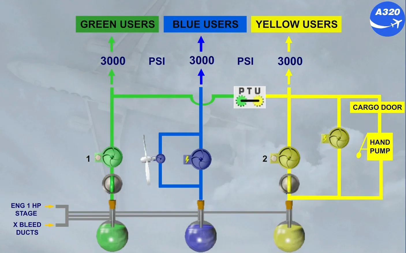
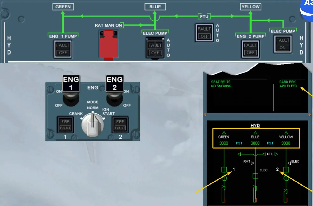
The A320 family has three independent hydraulic systems:
- Green
- Yellow
- Blue.
Let’s look at each system in more detail.
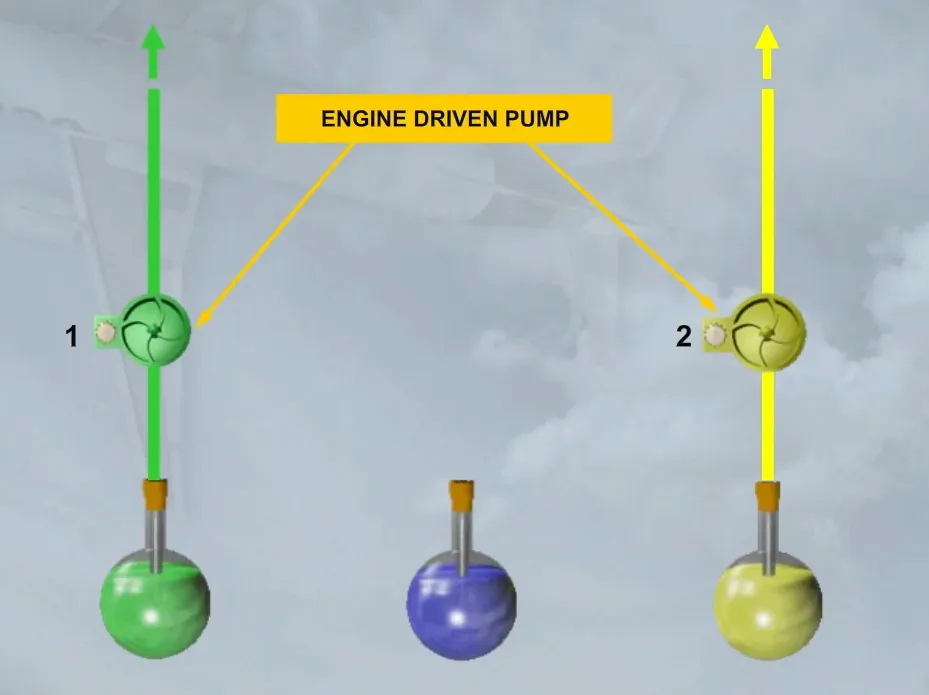
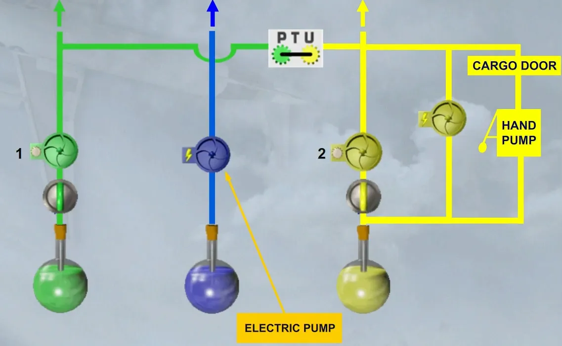
The green and yellow hydraulic systems are each pressurized by an engine driven pump.
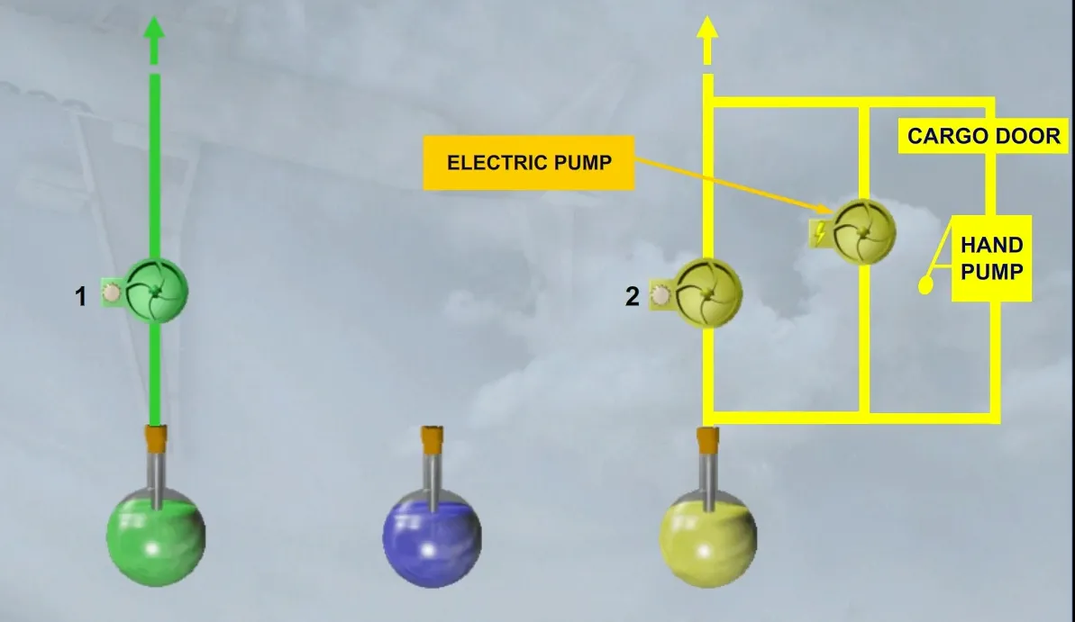
The yellow hydraulic system can also be pressurized:
- By an electric pump, which allows the yellow hydraulics to be used on the ground when engines are stopped
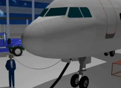
- By a hand pump, used by crew members in order to operate the cargon doors when no electrical power is available.
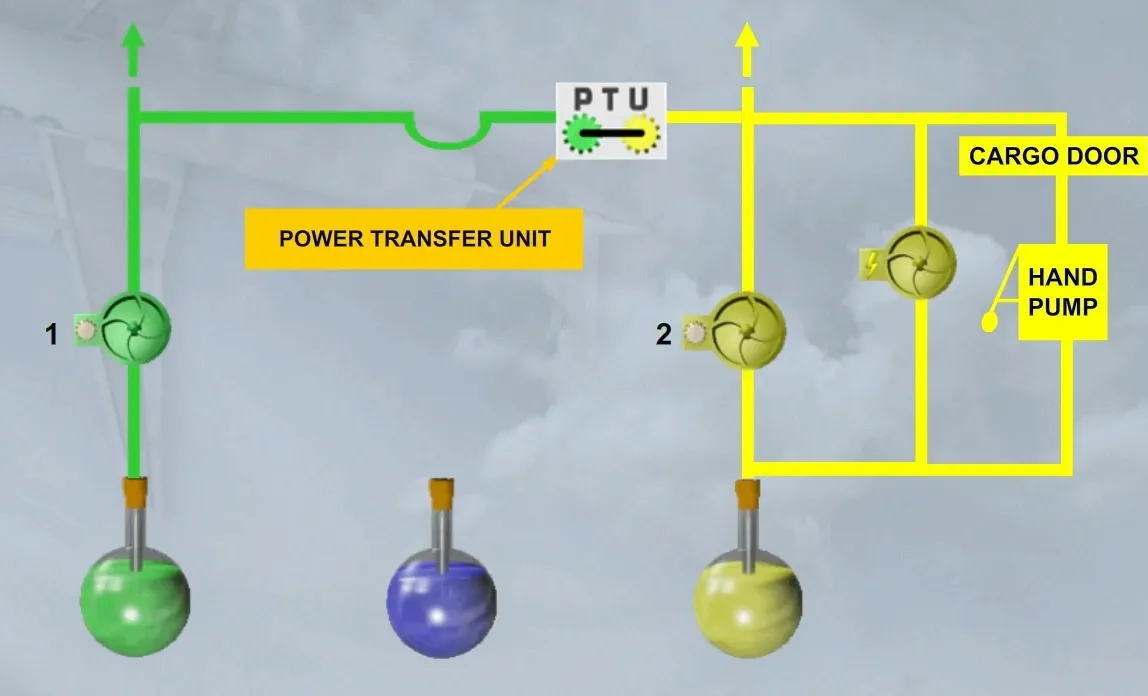
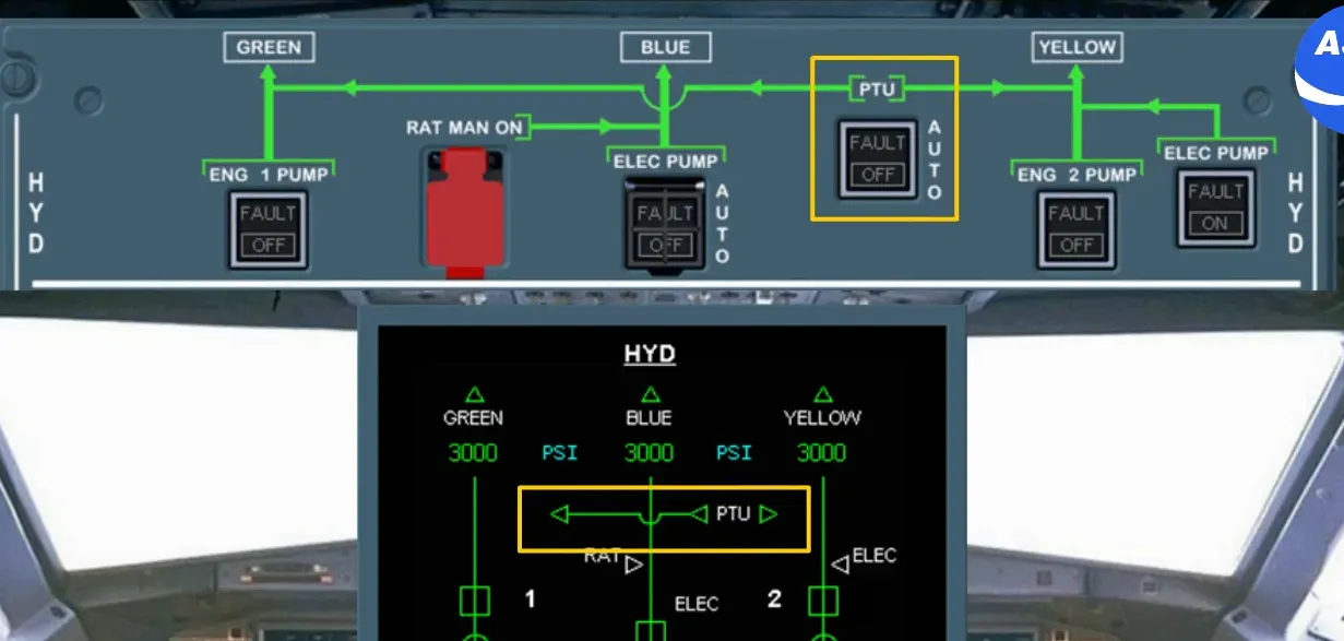
A bidirectional Power Transfer Unit (PTU) enables the green and yellow system to pressurize each other automatically, as soon as a differential pressure is detected.
Note: There is no fluid transfer.
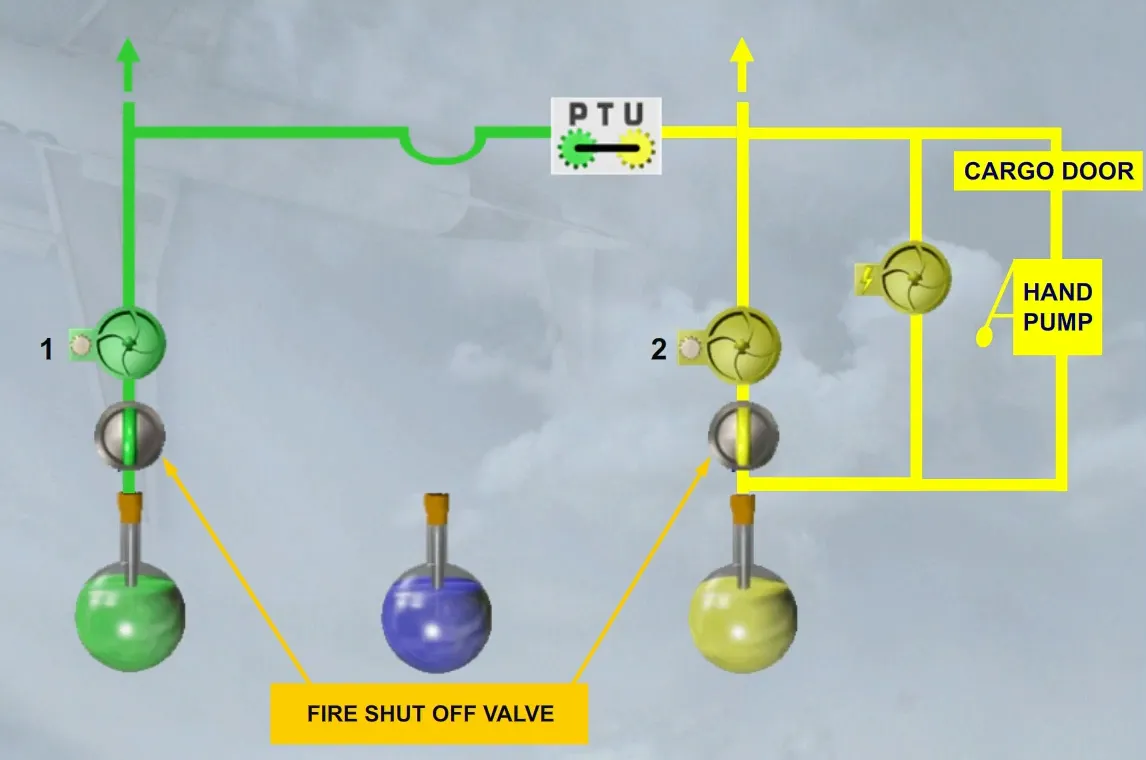
Fire shut off valves are installed between the reservoirs and the engine driven pumps.
Each valve is controlled to close by pushing the related ENG FIRE pushbutton.
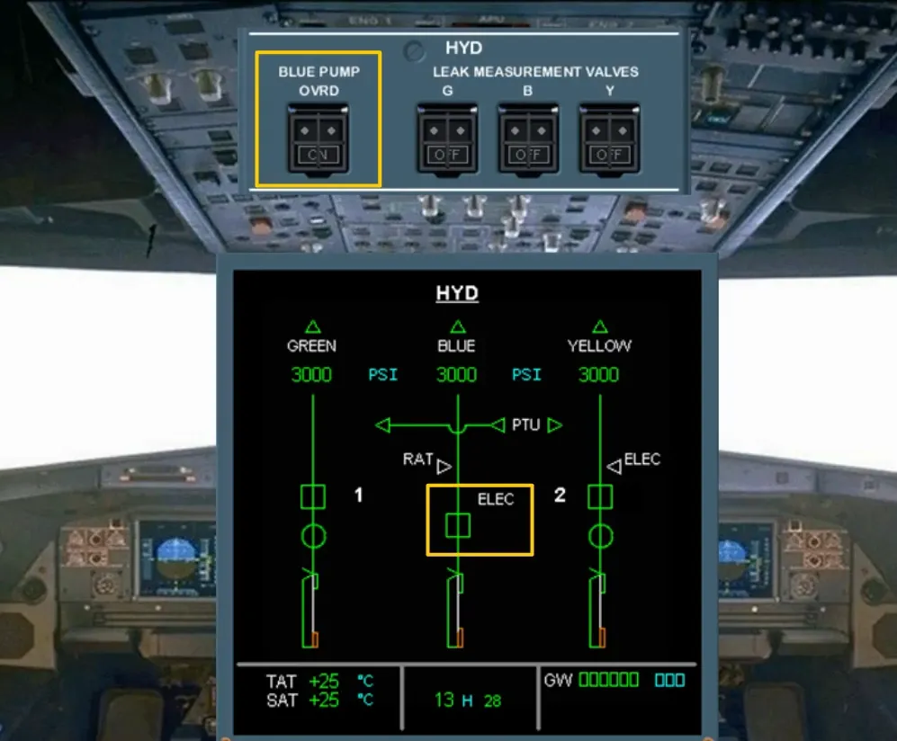
The blue hydraulic system is pressurized by an electric pump provided the normal AC power is available:
- In flight, or
- On ground with at least one engine running.
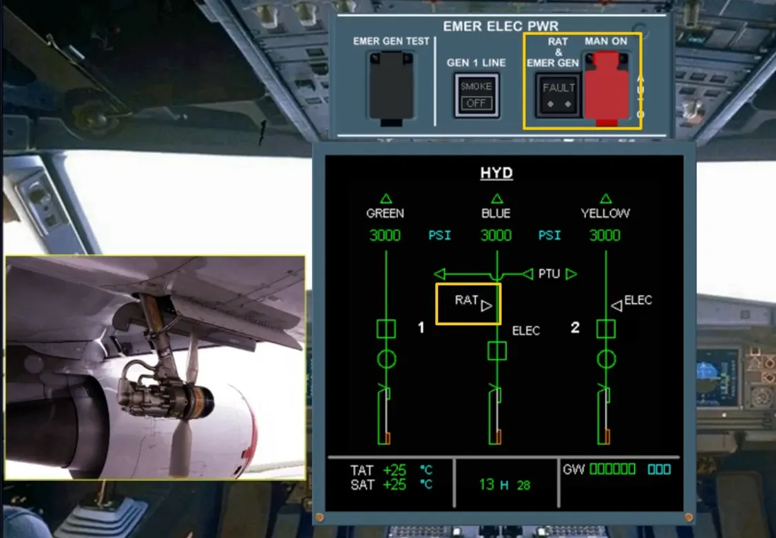
In an emergency the blue system can be pressurized by a pump driven by a manually extended Ram Air Turbine (RAT).
Note: If the AC BUS 1 and 2 are lost, the RAT is extended automatically and its driven pump delivery pressure is coupled to the emergency generator (refer to the ELECTRICAL SYSTEM).
Each hydraulic system delivers a constant pressure to the users.
Note: The hydraulic reservoirs are maintained pressurized to prevent their pumps cavitations, using reduced bleed air from the engine 1 HP stage or from the crossbleed ducts.
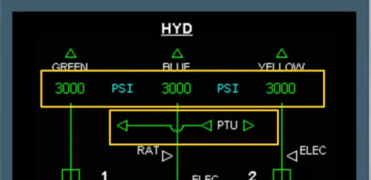
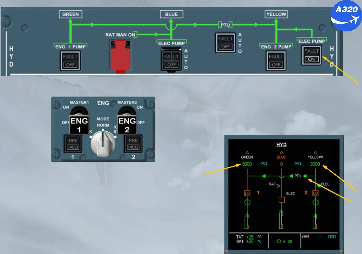
The components we have talked about are displayed on the ECAM HYD page except the hand pump on the yellow system.
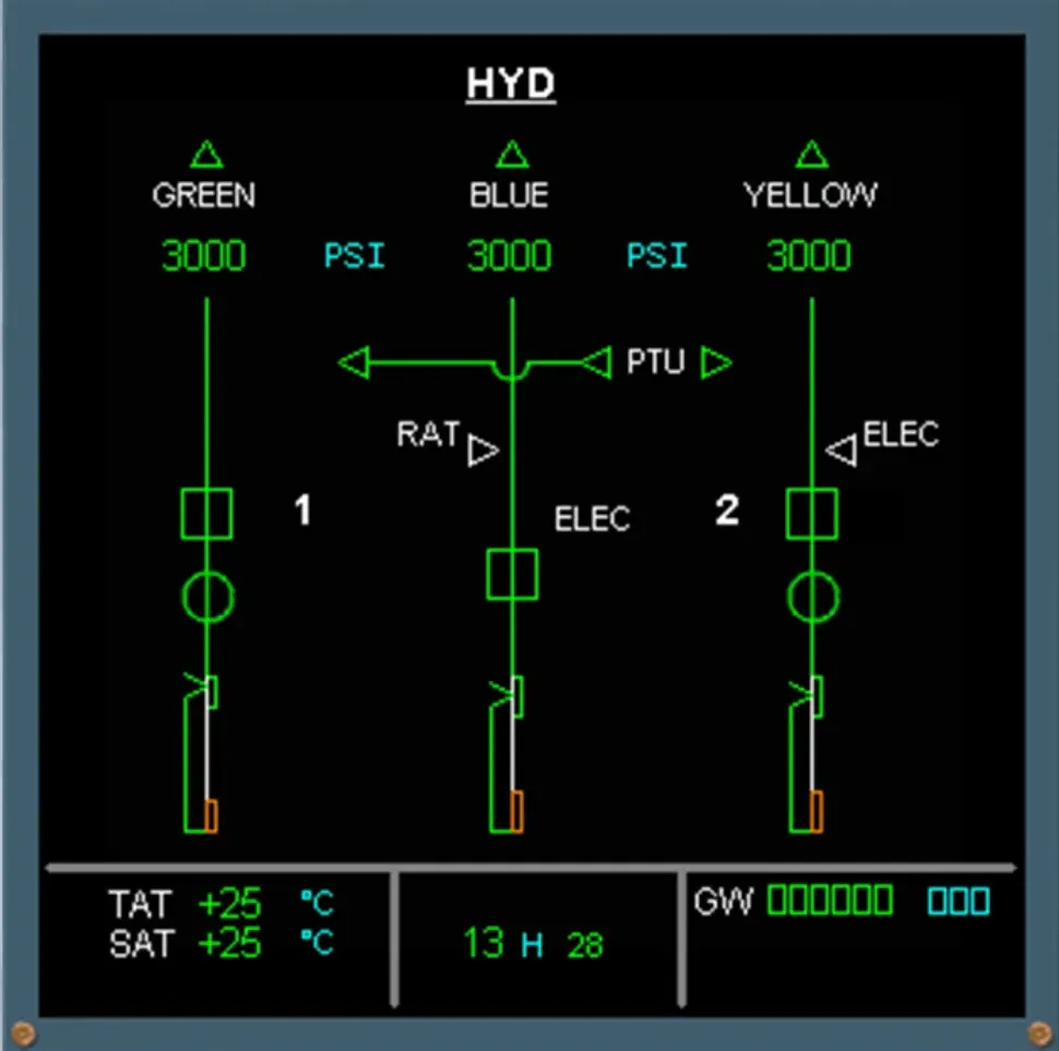
Let’s briefly review the basic system using the ECAM HYD page:
- Reservoirs
- Fire shut off valves …
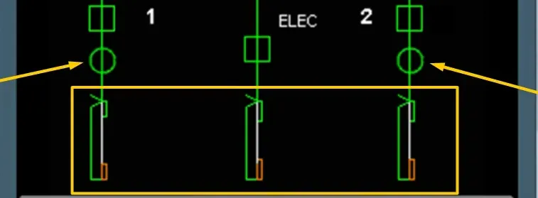
- Engine driven pumps
- Electrical pumps
- RAT …
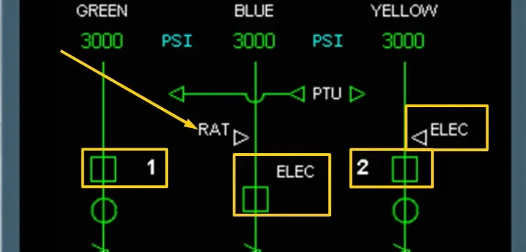
- PTU
- Pressure indications.
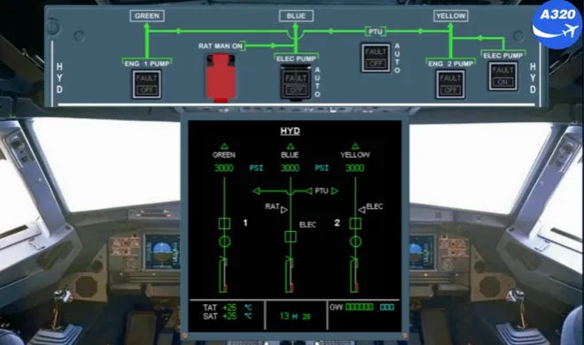
The controls of all the components we have talked about are located on the overhead HYD control panel. Let’s now compare the ECAM HYD page with this panel.
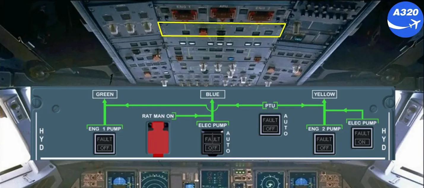
The hydraulic system is fully automatic. However each pump and the PTU have an associated pb-sw for abnormal operation.
Each engine driven pump is controlled by a pb-sw located on the overhead panel.
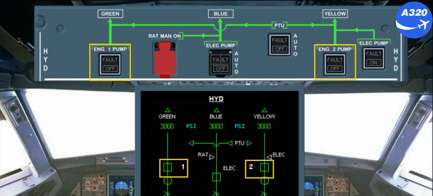
Each electrical pump is controlled by a pb-sw.
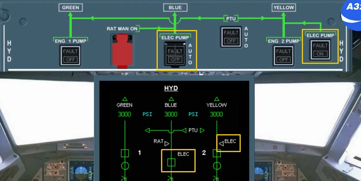
On the right hand side of the overhead C/B panel, an additional control allows the blue electric pump to run prior to engine start.
The PTU is controlled by a pb-sw.
The RAT may be extended manually by using this guarded pb.
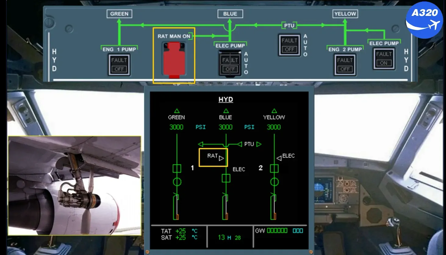
The RAT can be also extended manually by using this guarded pb, but in addition, the emergency generator will be on line (refer to the ELECTRICAL SYSTEM).
Let’s look at things pilots need to know about the hydraulic system during normal operation.
The hydraulic system is fully automatic during normal operation.
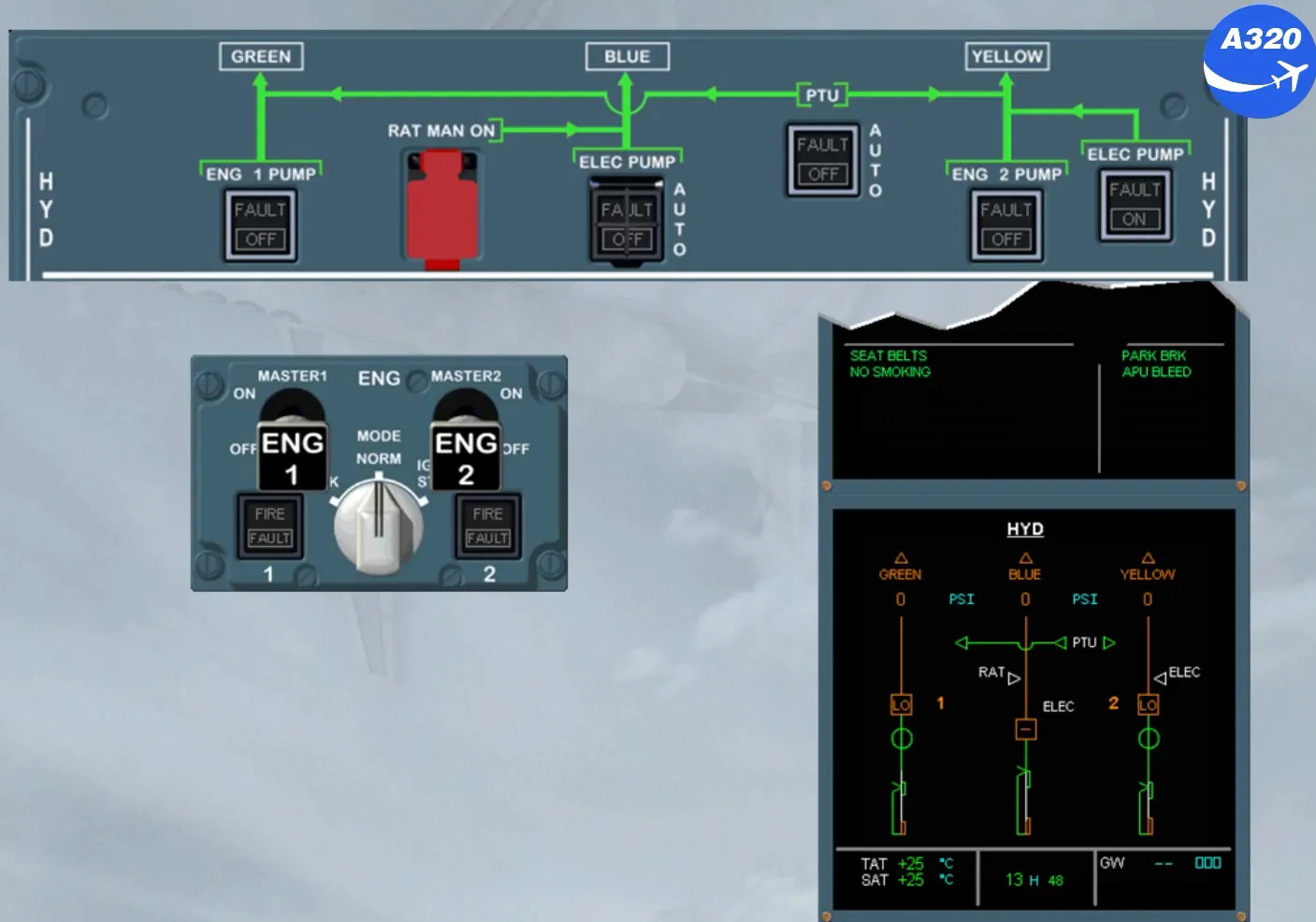
During preliminary cockpit preparation, do not pressurize the hydraulic system without clearance from ground crew.
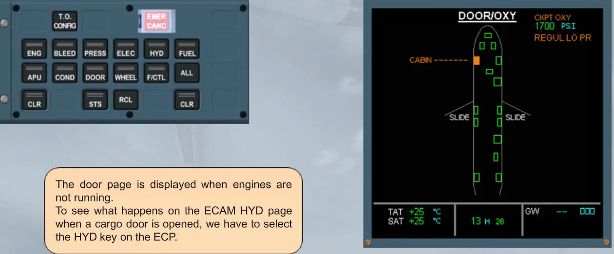
The door page is displayed when engines are not running.
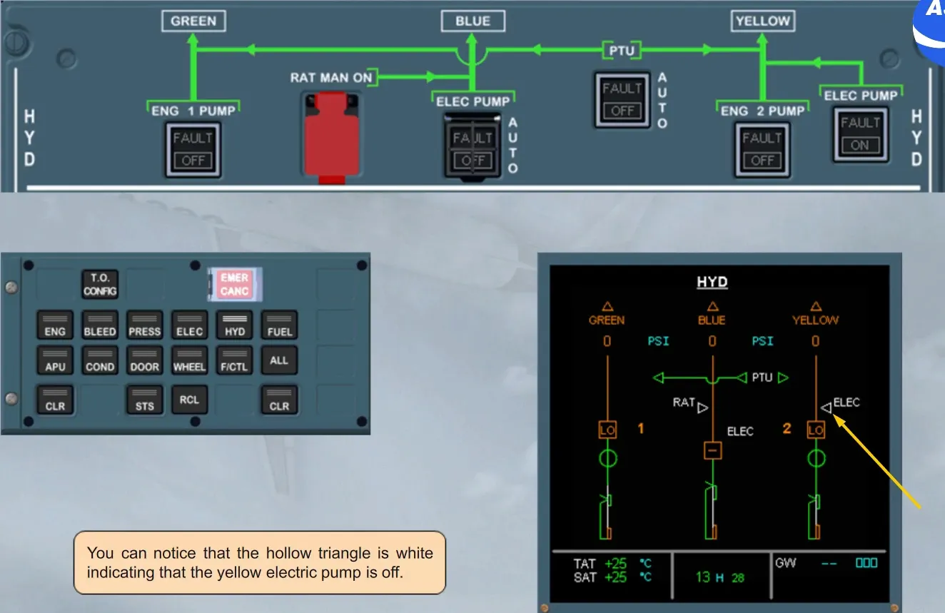
To see what happens on the ECAM HYD page when a cargo door is opened, we have to select the HYD key on the ECP.
You can notice that the hollow triangle is white indicating that the yellow electric pump is off.
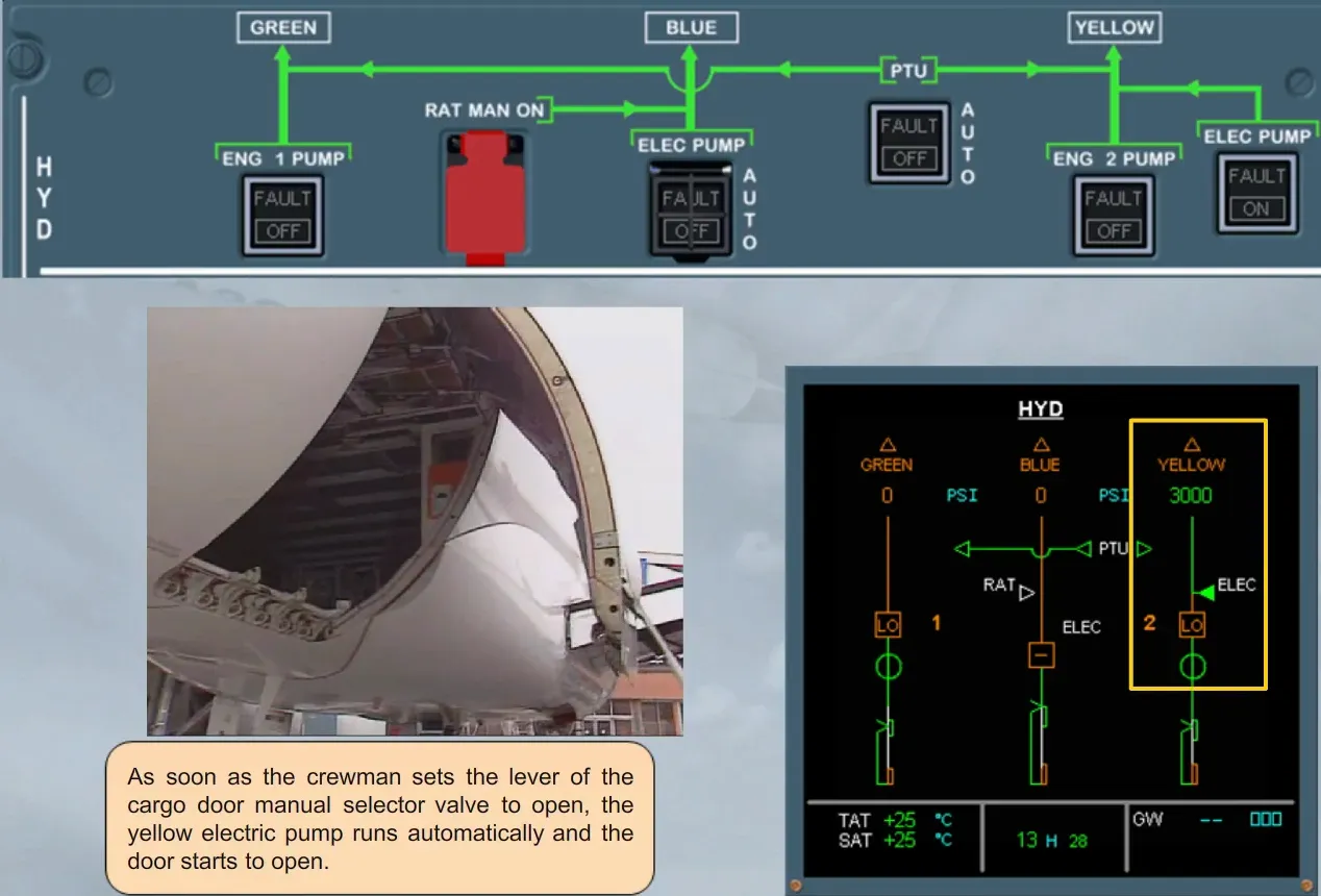
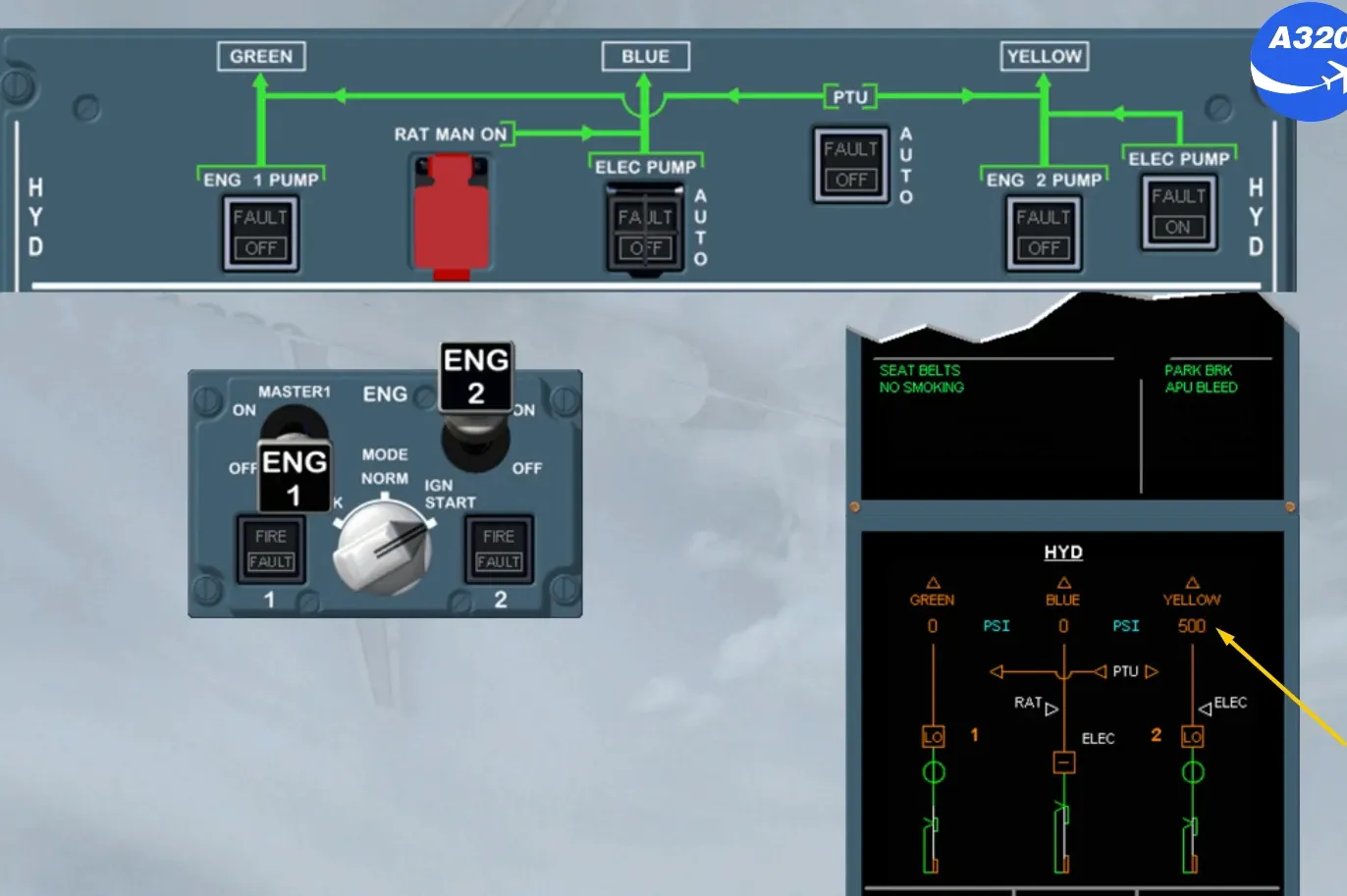
As soon as the crewman sets the lever of the cargo door manual selector valve to open, the yellow electric pump runs automatically and the door starts to open.
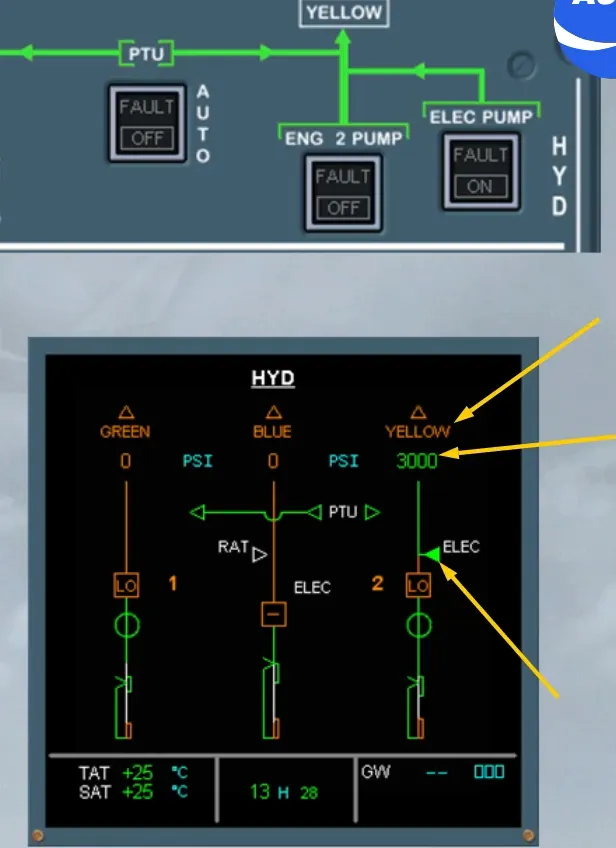
Observe on the ECAM SD page that the yellow hydraulic electric pump triangle has changed from hollow white to solid green indicating that it is running.
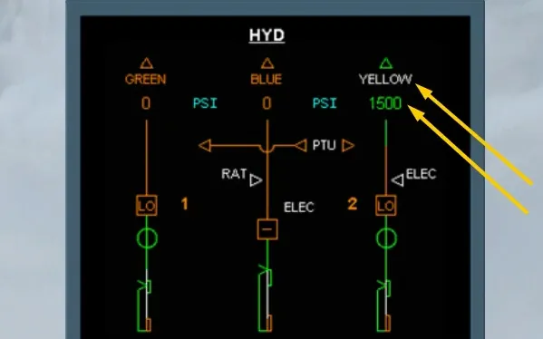
The yellow system pressure has increased from zero amber to 3000 green providing pressure to operate the doors.
The yellow system is not fully pressurized as indicated by the system identification remaining amber.
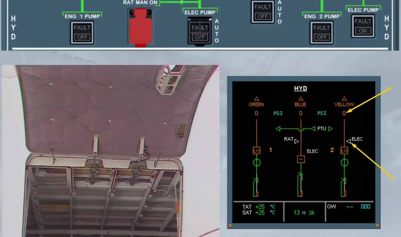
As soon as the door is fully open the yellow electric pump stops.
Notice that the yellow electric pump is now hollow white. The pressure has dropped to zero indicating that the system is totally depressurized.
The process will be the same during the cargo door closure.
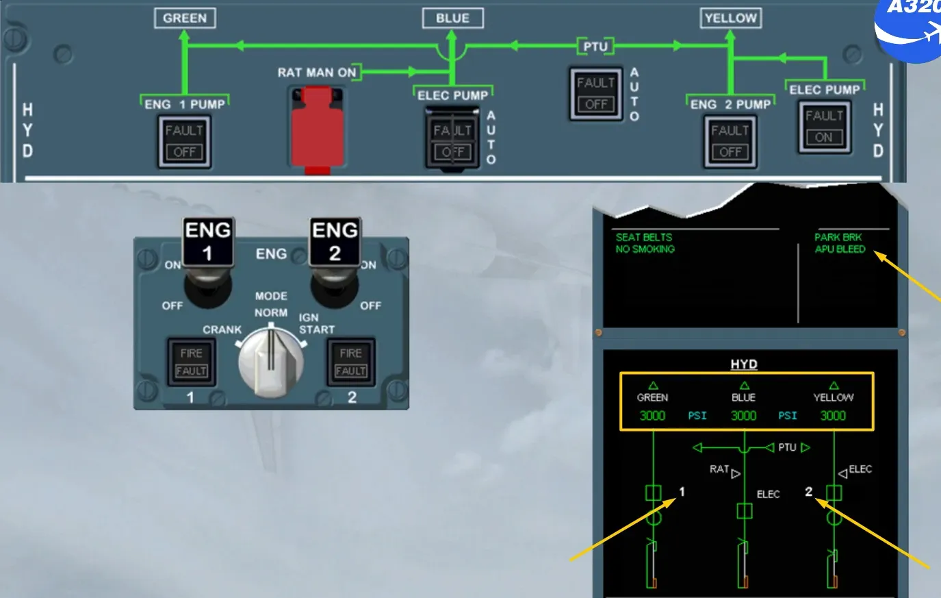
Notice that if the yellow electric pump is manually switched ON, the yellow system is pressurized, as shown and as both ENG MASTER switches are off, the PTU runs and so the green system is also pressurized.
As you already know, during engine start, the ENG page is displayed on the ECAM System Display.
Here for training purposes, the HYD page is displayed to see the automatic operations of the hydraulic system during start but, more importantly, to learn the indications on the ECAM HYD page and their meaning.
We will start engine 2 for you.
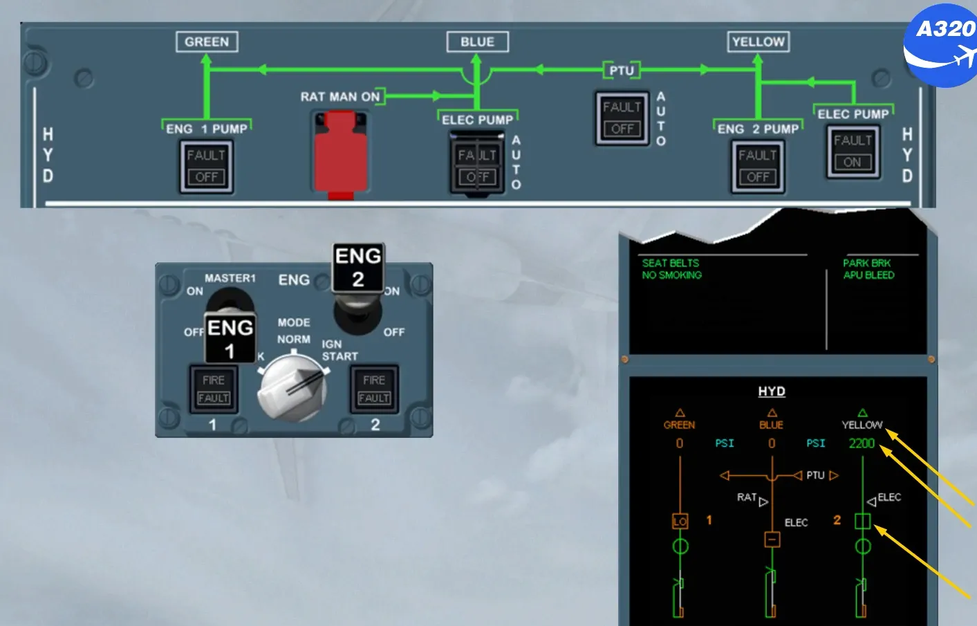
The yellow pressure starts to increase indicating that the engine driven pump is starting to pressurize.
Yellow system identification will change from amber to white, indicating that the yellow system is available (as soon as pressure is above 1450 psi in green).
The yellow engine driven pump changes from LO amber to in line green (as soon as pressure is above 2200 psi).
Then, the yellow pressure increases to the normal operating pressure which is 3000 psi.
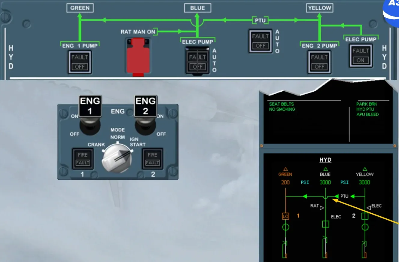
Note: The PTU indication has changed to amber, because its operation is inhibited during the start of the first engine.
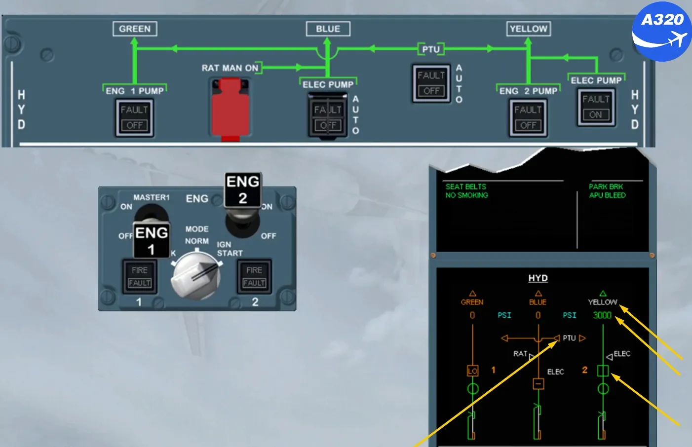
Before the end of the first engine start sequence, the pump legend changes to white indicating that the related engine N2 is not below idle.
Simultaneously the blue electric pump starts automatically and pressurizes the blue hydraulic system, as shown.
Notice that the PTU is not running even if the differential pressure between the green and yellow is greater than 500 psi. Because the parking brake is on.
Note: In this configuration, the PTU will run if the parking brake is off and the nosewheel steering is not in towing position.
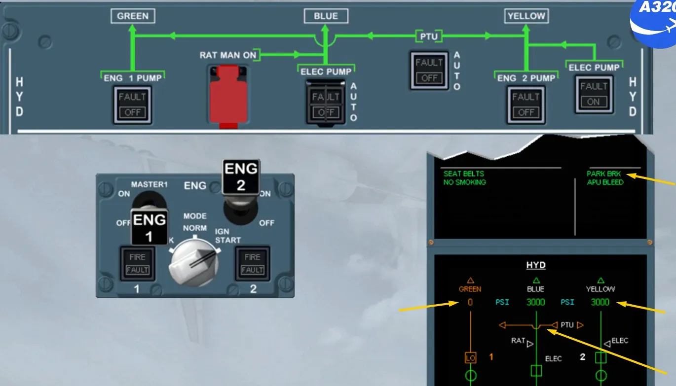
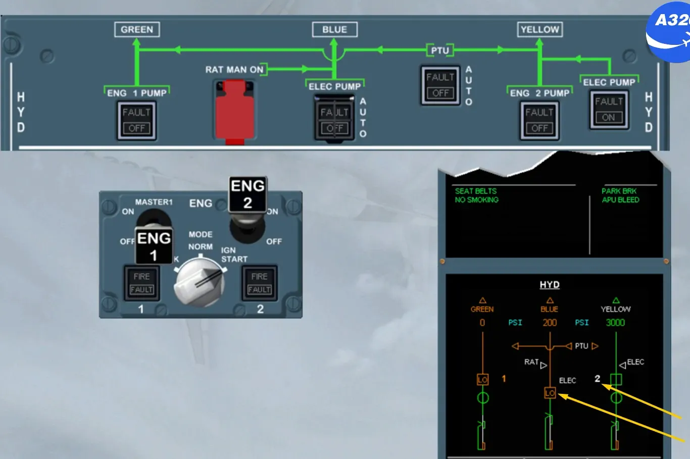
Let’s now start engine 1. During this sequence, observe the PTU indication as well as green hydraulic system indications.
As soon as the ENG MASTER 1 switch is set to ON, the PTU runs and pressurizes the green hydraulic system as shown.
Note: A green memo message indicates that the PTU is running.
The PTU stops when the differential pressure between the green (from the engine 1 driven pump) and the yellow is less than 500 psi.
This momentary operation of the PTU is used as a test.
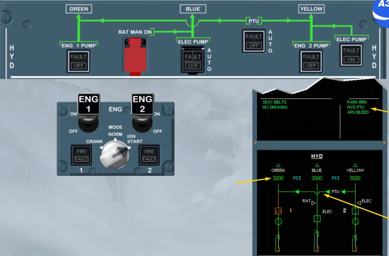

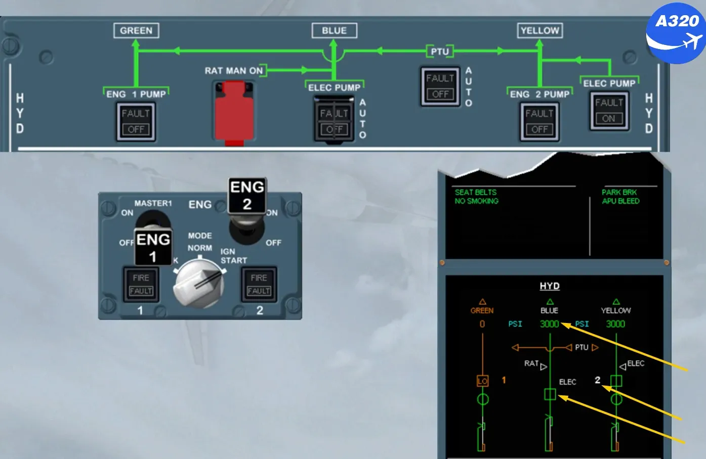
Once the start sequence is complete:
- Both pump legends are in white
- As the PTU is stopped, the green memo HYD PTU is removed
- The three hydraulic systems are supplied normally.
Module completed